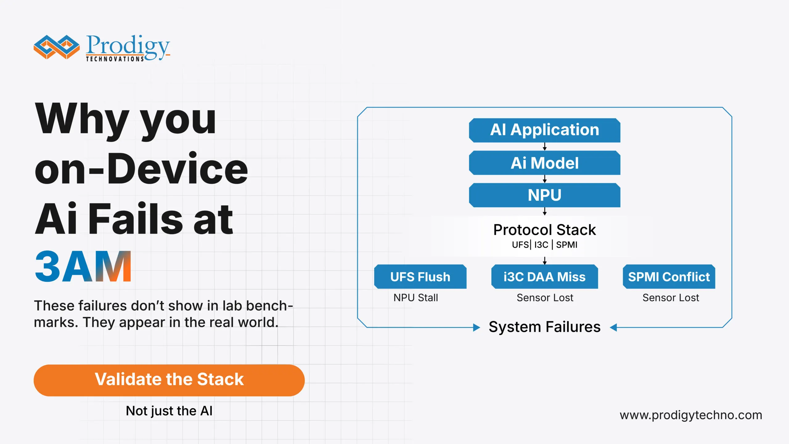
The AI model is fine. The protocol stack down it is not.
The flaw of It Works in the Lab.
All of the on-device AI capabilities are verified during shipments. Face recognition gains straight off. The on-demand voice model is an immediate response. Real time camera processing is at full frame rate.
The stories from users three months later tell otherwise.
The AI feels “slower.” Face unlock constantly stops working. Life is not as promised by battery life. Users do not report that there was a particular failure. They complain of a feeling that the device is not as good as it was in the first day.
The AI model is not the root cause in practically every case that we have examined. It isn’t the NPU. The protocol stack is only the level that lies between the silicon and the data and the circumstance that no one tested it out in conditions similar to the ones it will be used in real life.
In this post, we discuss three common types of failures that can be observed in any mobile AI program: a storage protocol crash due to an AI workload, sensor bus crash due to thermal stress, and power management conflict due to concurrent AI workloads. Each one is preventable. All of them are not visible without the correct tools of visibility.
Failure Mode 1: UFS Storage Corrosion by Under AI Inference Load.
What the datasheet says
Write Booster paired with UFS 4.0 has a write speed up to 2,800 MB/s with a linear speed of 2,300 MB/s. Burst writes are absorbed by the SLC cache. The system is quick, energy-saving, and prepared to meet the requirements of the AI-workloads.
What actually happens
Write Booster is a performance gift that has a cost delay. The SLC cache is finite. User storage fills up to 6070 percent capacity which occurs over a few weeks with most users utilizing AI-intensive apps the company ware is forced to empty the cache back to TLC or QLC NA ND to clear the way to the next burst.
In that flush, three items get concurrent that do not appear in any datasheet benchmark –
The initial step to allow the data flow between the management and the internal data flow is that the M-PHY link goes into a management state. When loading model weights into a storage is happening to an AI inference task, the weight loads conflict with the flush to occupy link bandwidth. The NPU does not demand very hard, it only decelerates to a sluggish degree that the AI feature becomes slow. This spike of latency is not seen in a log file. It appears in a user review.
Second, when the UniPro Power Mode logic is not calibrated accurately, one would get a failure when the device enters the Hibernate mode in the case of flush cycles. The storage link remains half-active so that it has on power but does not do useful work. The consequence is destined validation engineers refer to as a zombie drain: a battery discharge rate that is 20–30 percent even greater than a spec guarantee, and is purely a result of a power state change that looks good when it is isolated but is ineffective when real combined workloads are involved.
Third, due to the SLC-to-TLC mapping fracturing with time the Host Performance Booster (HPB) mapping table becomes error-correlated. The HPB is created to speed up the performance of a random read by caching a map of commonly used logical block in host DRAM. By the time that map flakes apart, there are progressive increases in the latency of data fetching that make the previously AI-perceptive Day 1 feature seem visibly sluggish by Day 90.
None of this amounts to a hardware defect. That is all a foreseeable side effect of the Write Booster architecture in practice and that it is all completely avoidable should the validation team be in a position to view what is actually going on in the protocol layer.
What justification must embrace.
Write Booster under concurrent AI inference loads Write transition Write transitions under concurrent AI inference loads Not operated under only synthetic write benchmarks.
- UniPro decode Power Mode when entering and leaving background flush cycles View of PACP indicates the link in a clean or partially suspended state.
- Distribution of Latency range across the entire storage fill curve not peak latency, and not averages. The 99 th percentile at 70 percent fill during the load of the AI is the number which reflects what the user thinks they will perform at 6 months.
The PGY-UFS 4.0-PA is capable of giving M-PHY, UniPro, and UFS instantaneous cross-layer correlation over a single time-stamped view. In a configuration where a Write Booster command is chosen on the UFS layer, the software correlates automatically down to the state transition of the M-PHY that caused theWrite Booster command. Visually, engineers are able to determine whether the workload on AI inferences and the storage flush are interacting and precisely where the latency cost is being incurred.
Failure Mode 2 – I3C Sensor Security Under Thermal Stress.
The failure that is only experienced in the field.
I3C was created as a replacement of I2C due to the sensor-rich nature of the modern mobile devices that are currently providing faster speeds, less power consumption and in-band interrupts. In case of AI-driven capabilities that require the use of multiple sensors at the same time (face recognition, gesture detection, always-on camera), I3C is the bus which enables the architecture.
The bus is also the one that produces a category of failure that is extremely hard to replicate in a laboratory.
Dynamic Address Assignment (DAA) is the most insecure. Contrary to I2C, where addresses of the devices are determined during the design, I3C devices will allow their addresses to be determined on-the-fly each time the bus is reset. In a mobile device that wakes up in deep sleep the bus reset occurs in milliseconds and it occurs when the device may be in a different thermal state than when the device went to sleep.
Within one of the programs that we enabled, one out of every 12 units shipped would fail: a deep sleep cycle longer than 45 minutes later the ENTDAA (Enter Dynamic Address Assignment) sequence would not be responded to by one of three sensors attached to the I3C bus. As far as application processor is concerned, the sensor just was not there. The AI feature relying on the sensor in this instance, face unlock would not work without any notice.
The bench test environment was able to replicate the failure all 500 test cycles with no difference. The thermal recovery curve of an inactive device that spent 45 or more minutes in the pocket of a user just did not agree with a 5-minute idle cycle done by the lab work.
Once the correct thermal soak conditions were recreated and the I3C bus reset was recorded on the PGY-I3C-EX-PD throughout the ENTDAA sequence the failure could be observed right away: a 10µs timing window where the sensor was responding within the assignment of its address and yet not within the acceptance threshold of the master. The fix took 4 hours. It took 3 weeks to rediscover the failure condition.
What confirmation must have found?
- DAA tests in realistic thermal operation conditions in particular, cold-soak, and extended idle conditions recreating the state of the device at the end of real user idle states, not only bench idle tests.
- When there is a multi-sensor concurrent wake condition on in-band interruption (IBI) when multi-sensors are all trying to signify the master at the same time, arbitration decides which sensor is granted priority, and whether or not any sensor address allocation is missed.
- Bus reset behaviour following long-term deep sleep the master-to-slave timing tolerance decreases with lower temperature and must be tested over the operating temperature range, not only at the typical room temperature Bus reset behaviour: This should be tested over the operating temperature range and not just at the standard room temperature.
Failure mode 3 – SPMI Power Arbitration Under Simultaneous AI Load.
The bus which links the Application Processor and the 5G Modem to the Power Management IC (PMIC) is the System Power Management Interface (SPMI). All Dynamic Voltage and Frequency Scaling (DVFS) events upon each NPU activation at inference task, each time the modem changes its power state when performing a 5G handoff is a SPMI-bus command.
One SPMI transaction is easy and quick all by itself. The SPMI bus is made a contested resource under mixed AI workload, modem activity and thermal management activities.
Its failure mode is arbitration deadlock: the CPU and the Modem are both commanding the same power-rail at the same time, and the arbitration logic in the firmware falters in resolving the conflict than the time the NPU would have taken to raise the power level. This leaves the brownout rather than the crash, but the inference task will fail with no notice or give incorrect results.
In the case of consumer AI features, this can be seen through the form of sporadic incorrect recognition outputs, the AI feature occasionally displaying stutters when running in real time, or the AI feature silently devolving to a lower-precision model without informing the user. These are intermittent failures that are thermal and load-specific and hardly ever repeatable at the bench without the specific combination of NPU load, modem activity and ambient temperature that causes the failures to occur in the field.
To prove the validity of SPMI power arbitration under AI workload it is necessary to observe the bus at the times of co-occurring NPU inference, modem 5G handoff and thermal management occurring. The PGY-SPMI-EX-PD offers microsecond-degree timing overview into the SPMI transactions, which enable engineers to see precisely how extensive a power command waits on the arbitrization queue before it is executed, and whether any NPU power ramp is being withheld because of modem priority traffic.
Why “3am” Is Not Just a Metaphor
This title of this post is not a disinvented one. The conditions of failure which are most significant in terms of on-device AI are the ones that happen not within a controlled environment: the phone that has been constantly running during a lengthy commute, the thermal situation that can only happen after 6 months of uncontrolled usage when the storage space is 72% full.
By definition, lab validation is unable to simulate all real-world conditions. However, it will be capable of simulating the state of failure that will be important when the validation team can see the protocol-layer and are aware of what to expect.
The three recovery scenarios presented in this post UFS storage breakdown due to AI inference load, I3C sensor bootstrapping due to thermal loading, and SPMI power arbitration due to identical AI workload are not conceptual. The three have been witnessed in all production programs. The three were all out of sight of tools used to monitor the system level. All that was evident in protocol-layer traced out when the right tools and conditions were involved.
On-board AI is no NPU problem only. Most of the risk is at the protocol stack and it is a system validation problem.
The implication of This on Validation Teams.
Three of the practical changes that would enhance AI feature validation coverage without making VC evaluation cycle substantially longer:
- Test on real fill not empty store. Test the device storage with 6575% capacity of data storage. It is the mark where the Write Booster behaviour of flush starts becoming significant. The majority of validation laboratories operate equipment at 10-20% fill that is not reflective of the equipment condition 3 months into the actual operation.
- Duration idle should equal actual user behaviour. There are thermal and time-dependent I3C DAA failures. A 5 minutes idle cycle at the bench does not mimic a 45 minutes pocket idle. Include additional idleness sequences to I3C validation test suite, which includes cold-soak, extended-idle, and thermal-stress conditions.
- Arbitration SPMI must be validated with both combined load and not isolated transactions. The failures of SPMI with AI load only manifest themselves when NPU, modem and thermal management systems are at work. An SPMI validation with combined load, monitored with a timing resolution of µs, captures the arbitration conflicts which isolated testing does not capture at all.
The protocol stack below the AI chip is just as good as the AI chip itself. Validate the stack.