I3C Protocol: Test Setup for Electrical Validation
I3C devices are going through mass adoption at the moment. One challenge however remains for I3C devices is interoperability. The I3C devices need to work with devices of other manufacturers. Electrical validation of the physical pin level signaling plays a critical role in the Interoperability of the I3C Devices.
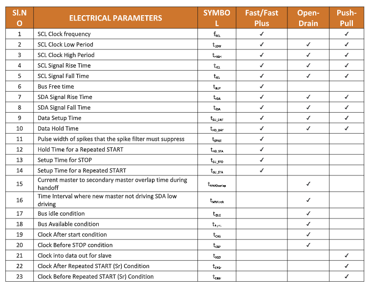
There are many parameters to the validated from an electrical validation perspective. However, some of the key parameters are listed below.
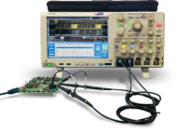
To capture I3C Signals for electrical validation, we need an oscilloscope with passive probes along with Prodigy PGY-I3C Electrical Validation and Protocol Decode Suite. The Oscilloscope and Probe bandwidth determines the measurement reliability.
The setup for the Electrical validation of I3C is as follows:
Hardware: Oscilloscope, this helps capture the signals required for electrical validation.
Software: The protocol validation suite measures the signal values and compares them with a specification to ensure compliance.
How to Setup the Hardware:
While selecting a scope, we must consider the minimum timing parameter that has a maximum impact on the oscilloscope bandwidth. In this case, the minimum timing parameter is 3ns rise/fall time. To measure this rise time, we need a scope with a bandwidth of 500MHz or more. Theoretically, the rise/fall time measurement capability of a 500MHz oscilloscope is 700ps. Considering the industry thumb rule, to measure a rise time of 3ns, we need at least 4 to 5 times the scope bandwidth. Hence 500MHz Analog bandwidth is recommended.
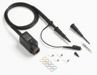
However, the entire test setup bandwidth is dependent upon the oscilloscope and probe bandwidth. If we use lower bandwidth probes, then the RT/FT measurement capability is limited by the probe bandwidth instead of the oscilloscope. Hence, 1GHz passive probes with 2 to 3pf of capacitive loading are recommended so that the test setup is least intrusive.
Another important parameter to be considered for accurate measurement is the sample rate of the oscilloscope. For accurate measurement of rise and fall time, we need at least 5 to 6 samples on the rising or falling edge. Here, the signal is to be sampled at 500ps timing resolution. Hence, an oscilloscope with a sampling rate of 2GS/sec is recommended. Some of the oscilloscopes use efficient interpolation techniques and can provide better measurement even at around 1GS/sec
To make reliable measurements, it is advisable to capture the complete I3C frame in the acquisition memory of the oscilloscope. An oscilloscope with longer acquisition memory enables users to capture a greater number of I3C frames resulting in more instances of measurements. This increases measurement reliability and enables robust product design.
How to Run the Software:
The PGY-I3C Software runs inside Tektronix to make oscilloscopes such as MSO5/6, DPO/MSO5000, DPO7000, and DPO/DSA/MSO70000 series oscilloscopes. The PGY-I3C Electrical Validation and Protocol Decode automatically makes electrical measurements and provides protocol analysis with a long acquisition record length of up to 125MB that provides superior I3C Protocol Analysis results at the press of a button.


