Introduction
The MIPI I3C Bus interface enhances the legacy I2C standard by reducing the number of physical pins required in sensor systems while supporting low-power, high-speed digital communication, similar to UART and SPI interfaces. This versatility allows for seamless integration with existing systems.
I3C is essential for integrating sensors in smartphones, IoT devices, and wearables, efficiently managing complex systems. It reduces costs and latency while enabling new functionalities through a unified management transport.
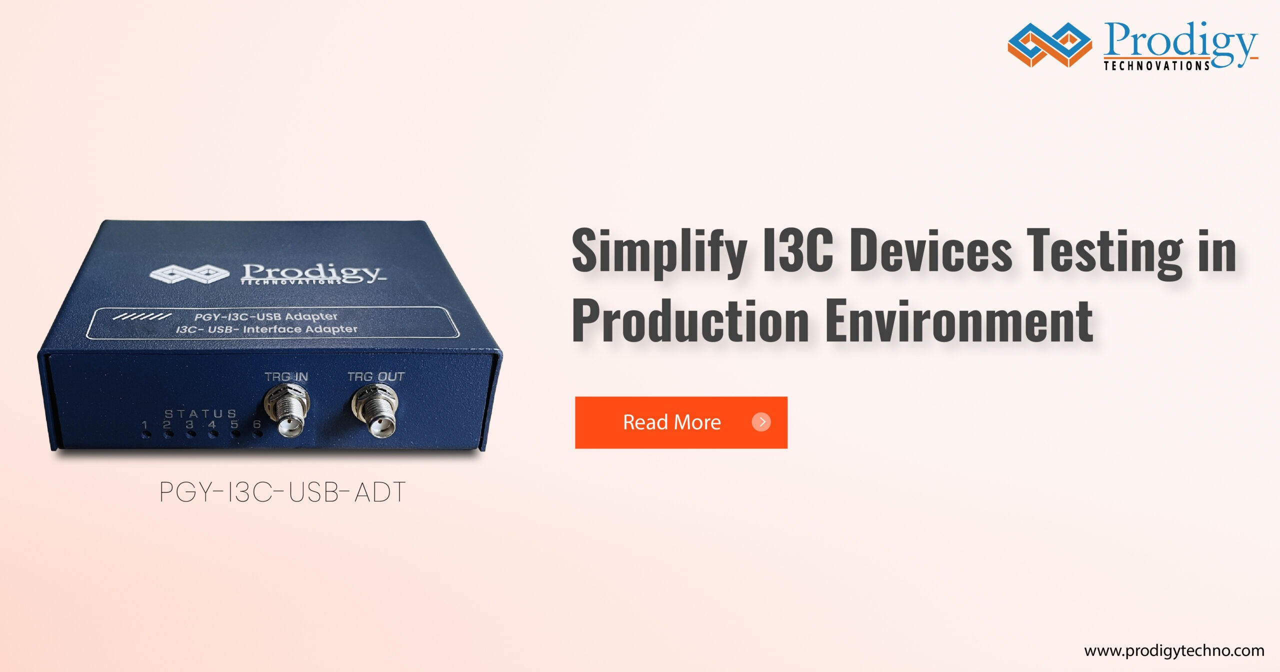
I3C based systems production benefit from using affordable I3C protocol analyzers like the PGY-I3C-USB- ADT, which enables efficient and automated benchmark testing and PASS/FAIL verification in production lines. Its programming interface, scalability, and reliable performance ensure accurate testing, thereby enhancing product quality and production efficiency. Prodigy Technovations offers a wide range of I3C testing products for IP development and pre-silicon to post-silicon validation and manufacturing testing.
This application note guides users through understanding the I3C interface and presents typical test cases, demonstrating how Prodigy’s Technovations solutions effectively address manufacturing teams need.
I3C Protocol Overview
The I3C protocol supports several communication formats, all utilizing a two-wire interface. The two wires are designated as SCL and SDA. SDA is a bi-directional data pin, while SCL can either serve as a clock pin or a bi-directional data pin in certain HDR modes.
All I3C communication occurs within a frame, beginning with a START condition, followed by one or more transfers, and ending with a STOP condition. The I3C interface supports Single Data Rate (SDR) messages, similar to I2C messages, with a maximum clock speed of 12.5 MHz. It also supports High Data Rate (HDR) messages, where data transfer is synchronized with clock cycles. There are two types of messages: Broadcast and Direct Common Command Code (CCC) messages, allowing the master to communicate with all or specific slaves on the bus.
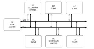
Figure 1: I3C Bus Diagram
I3C protocol is based on frame encapsulation approach. The I3C frame always include START, the Header, the data and the STOP. I3C bus always initialized in SDR mode and never in HDR modes. Common Command Code (CCC) commands protocol is formatted using only in SDR. CCC are transmitted to specific to slave or all slaves in I3C bus. CCC General format as shown in this figure.
At start up stage from power-down, main master shall assign unique dynamic address to every device on the bus including itself. Dynamic address creates a priority ranking of device interrupts. If any secondary master present in the I3C bus shall be made aware of dynamic address and characteristic registers. For more details on I3C protocols, please refer to MIPI® I3C specifications.
PGY-I3C-USB-ADT Applications
Use Cases for PGY-I3C-USB-ADT in Manufacturing
- Production Line Testing: Diagnose communication errors between I3C masters (controllers) and slave devices (sensors) during assembly, identifying faulty components or configuration
Key Considerations for Implementing PGY-I3C-USB- ADT
- API Integration: Opt for analyzers with API functions the user can create test automation for efficient data capture, analysis, and
- Support application frequency range as per I3C Spec, Commands, configurable as controller (master) or target (Slave)
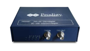
Figure 2: PGY-I3C-USB-ADT Hardware Device
Testing a I3C Master or Slave:
I3C DUT can be Master or slave. The API script runs in the host computer through any API environment can initiate I3C Traffic and response through the same. User can set up the Master or Slave characteristic registers of PGY- I3C- USB-ADT based on the requirement in DUT by Configuring the functions by modifying the API Script.
Figure 3:PGY-I3C-USB-ADT Test Setup
Using the API Script in PGY-I3C-USB-ADT software designers can initiate the communication with DUT. For example, user can send ENTDAA command which is instantiation command during the power up state. By running this API script Master (in this case PGY-I3C-USB- ADT) sends the commands to DUT.
Script forconfiguring Master and Slave:
if exercise.EstablishConnection() == eResponseFlag.Success: #Connection Establishment
print (“Connection Successful”) “””response = exercise.ResetAll() print”reset done”
time.sleep(1)
response =exercise.EstablishConnection()”””
response = exercise.AddNode(eNodeType.Master, 1.8) #Add Master
ifresponse == eResponseFlag.Success: print(” Master Added Successfully “) response =
exercise.AddNode(eNodeType.I3C_Slave,1.8,”6b”,0x208
006c900b,0x26,0,eDeviceType.Internal,eTerminationTyp e.ON,255) #Adding Slave(eNodeType,Voltage,”Static address”,PID,BCR,DCR,Interface,termination,255)
ifresponse == eResponseFlag.Success:
print(” Slave with Node ID= 1 addedsuccessfully “) response = exercise.StartCapture()
ifresponse == eResponseFlag.Success: print(” Capture Started”)
Once thecapturestarts, we willthen emulatethe I3C bus configuration.
In real world, I3C devices are expected to work in I3C bus configuration. Where there will be main master, I3C Slave. Hence it is important for design and test engineer to test the I3C devices in I3C Bus configuration.
PGY-I3C-USB-ADT can be configured has single master, single slave to address the need of emulating I3C Bus. User can setup the different characteristic registers of I3C devices in PGY-I3C-USB-ADT and configure the I3C Busalong with DUT.
We instantiate the I3C bus by sending ENTDAA command so that addresses are assigned and then we didwriteand readthedatafrom I3CSlave.
Scriptfor ENTDAA :
defloadScriptENTDAA():
response = exercise.FormMessageMaster(eFrameType.BROADCA ST,0,eTransferType.Read,9,[0],True,0x07)
ifresponse !=eResponseFlag.Success: print(exercise.GetResponseDescription(response))
else:
print(“ENTDAA sent successfully”)
Once after assigning the Dynamic address to the I3C slave, we are performing Private write and read operation to the slave using the private write and read commands.
Script for Private Writeand Read :
def Pvt_wr():
response =
exercise.FormMessageMaster(eFrameType.PRIVATE,1,eT ransferType.Write,0,[0x0f, 0x08, 0x09, 0x0A],False)
print(“Response Pvt_wr:”,response)
if response != eResponseFlag.Success:
print (exercise.GetResponseDescription(response)) else:
print (“Pvt_wr”) def Pvt_rd():
response =
exercise.FormMessageMaster(eFrameType.PRIVATE,1, eTransferType.Read,4,[0],True)
print(“Response Pvt_rd:”,response)
if response != eResponseFlag.Success: print(exercise.GetResponseDescription(response))
else:
print(“Pvt_rd”)
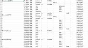
Figure 5: Report generated from the results
Once the script is run, the I3C-USB-ADT will generate a .csv file along with all the details such as frequency, time stamp, address, data , errors and save it in a defined path. This allows the user to easily verify test scenarios in the future by reviewing the report. Using scripting language user can compare the test results with golden reference data and decide pass/fail condition of the device under test.
The PGY-I3C-USB-ADT supports emulating and verifying all I3C commands according to the MIPI I3C specification. Configuration details for all commands are explained in the PGY-I3C-USB ADT User Manual, and users have the provision to write their own automation scripts for specific test scenarios.
Prodigy Technovations also offers a range of I3C protocol products, including the PGY-I3C-EX-PD (I3C Exerciser and Protocol Analyzer), which is characterization of I3C interface for protocol and timing performance in pre an dpost silicon validation environment. It is also an efficient too to debug the design issues in failed devices.
Additionally, Prodigy Technovations provides oscilloscope-based electrical validation software(PGY-I3C-EV-PD) for the I3C electrical parameter verification for open- drain and push-pull frequencies.
Another notable product is the PGY-I3C-EX-PD Lite, similar to the PGY-I3C-USB-ADT, but it includes GUI and API support for automation scripting. This tool addresses needs of application engineering team needs or application where you donot need to vary the timing and amplitude parameters as well not large test cases.
For more details about the range of I3C products, you can visit Prodigy Technovations.
Conclusion
I3C protocol analyzers are essential for manufacturers aiming to enhance product quality, optimize production efficiency, and streamline development processes. These analyzers offer comprehensive insights into I3C communications within devices, leading to a more dependable and robust production environment.
The industry-leading PGY-I3C-USB-ADT provides a powerful verification solution to address the testing challenges of I3C devices, including controllers and targets. In large chip and chipset manufacturing companies, the PGY-I3C-USB- ADT plays a significant role in product testing. It generates I3C protocol packets per I3C V1.0 (upgradable for upcoming specifications), offering a reference I3C device for comparative analysis and debugging.


