DDR5 is fifth generation dynamic random-access memory provides superior performance over DDR4. It is designed for next generation CPUs and GPU to address artificial intelligence applications and large data processing applications with fast access to the data.
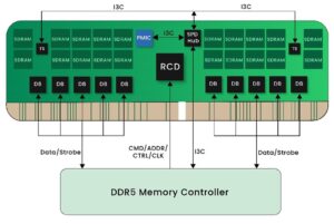
One of the key features of the DDR5 is power management integrated circuit (PMIC), which regulates the is power requirements of DDR5 memory module. PMIC generates the multiple outputs that required for DDR5 memory module. PMIC is managed by I3C or I2C bus interface that helps in low power consumption.
PMIC is managed using the serial peripheral detect (SPD) device. SPD communicates with PMIC using I3C. SPD makes it possible for the CPU to know which memory module is present and what memory timings to access. SPD also manages DDR Registering Clock driver (RCD) and temperature sensors (TS).
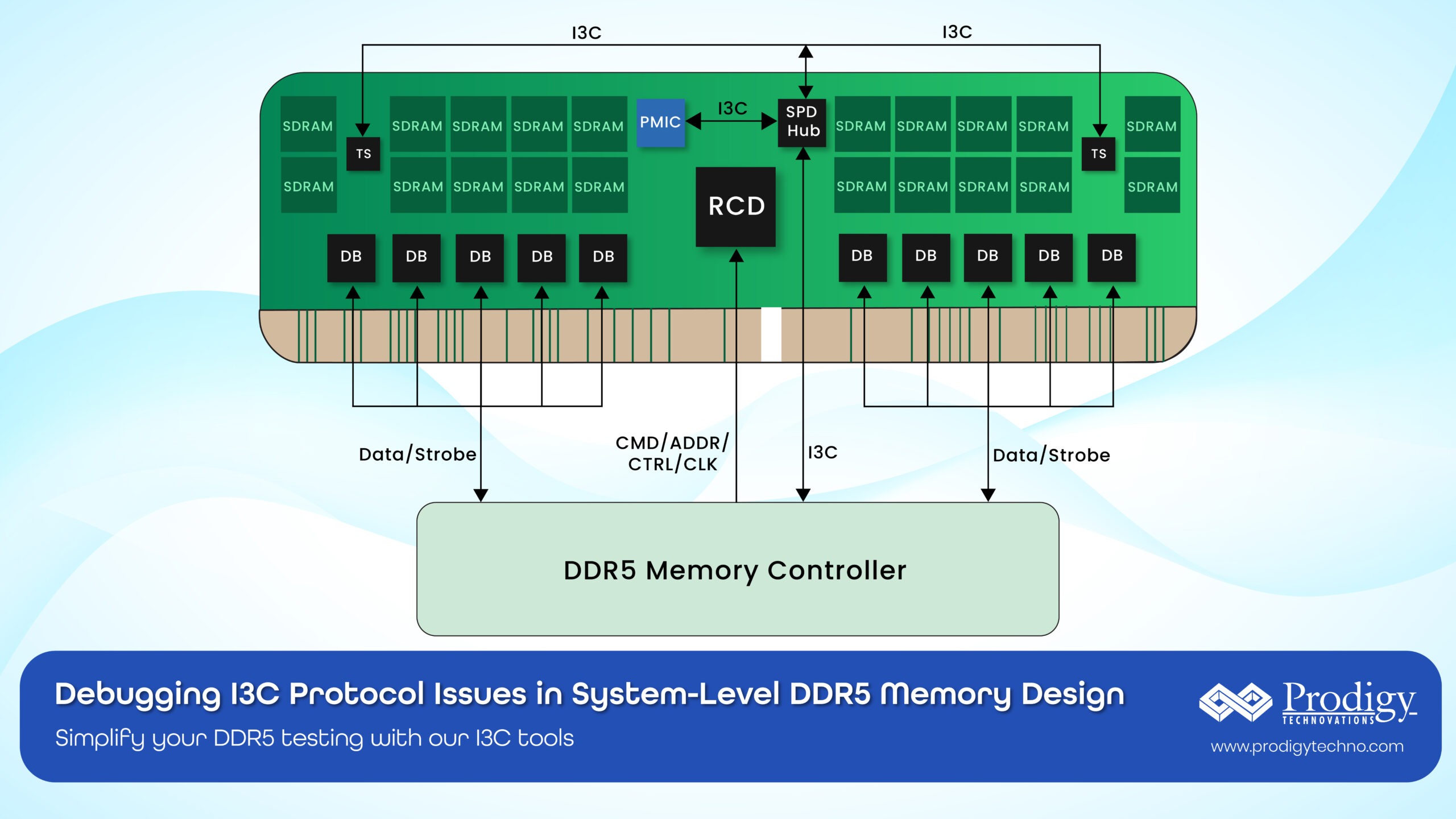
In a computer system application, the typical I3C bus network for DDR5 memory management is below
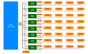
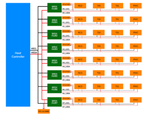
Host Controller Communicate with Serial Peripheral detect (SPD) using I3C bus. SPD provides the relevant information to host controller and manages the DDR5 memory performance by communicating with RCS, TS and PMIC for different DDR5 DIMMs using I3C Protocol. RCS, TS and PMIC are targets (Slaves) and respond to the query from SPD which operates as a controller or target.
I3C is improved Inter IC Communication bus developed by MIPI Alliance to address next generation applications. General Specification of I3C are
- Operates from 100KHz to 12.5MHz
- Signal Amplitude 1V to 3.3V
- Packetized protocol
- Multidrop bus network
- Different commands support for different used cases of I3C bus
I3C bus in DDR5 uses some of the following Common Command Codes
| Commands | Description |
| DEVCTRL | This Broadcast CCC (Device Capabilities) is a command that is used to control or modify certain operational behaviours of a device on the I3C bus, such as enabling or disabling specific features, setting operating modes, or adjusting device settings. Used to set certain operations such as enable or disable PEC, and Parity function to all Devices which are connected in I3C bus. |
| SETHID | This Broadcast CCC is used for assigning or updating the Host ID for a master device on the I3C bus in multi-host environment. |
| SETAASA | This Broadcast CCC allows the Controller to request that all connected Targets that have I2 C Static Addresses use their I 2C Static Address as their Dynamic Address. Used for assigning the Dynamic Address. |
| ENEC | This Broadcast CCC allows the Controller to control when Target-initiated traffic(IBI) is allowed (Enabled) on the I3C Bus. Used to enable In-band interrupt. |
| DISEC | This Broadcast CCC allows the Controller to control when Target-initiated traffic(IBI) is not allowed (disabled) on the I3C Bus. Used for disabling the In band interrupt (IBI) on the I3C bus. |
| RSTDAA | This Broadcast CCC indicates to all I3C Devices that the Controller requires them to clear/reset their Controller-assigned Dynamic Address. |
| DEVCAP | This Directed CCC is used to query or set the capabilities of a device on the I3C bus, such as its maximum data rate, supported features, and other operational characteristics. In SPD 5 Hub, Used to inform the host, whether the hub is support Timer based Reset or not |
| GETSTATUS | This Direct CCC is a Get request for one I3C Target Device to return its current Status. Used to inform the host about PEC error, Parity Error, and Pending interrupt information. |
Testing Needs of I3C controller and targets:
While designing I3C based products for DDR5 application, designers need different types of I3C testing tools to meet characterization and validation needs. For example, designers developing PMIC would need a I3C Controller which generates I3C protocol traffic compliant to I3C physical layer signal characteristics and protocol format. Designers also may need error injection capabilities in physical and protocol layer to ensure robust performance of I3C devices. Designers who develop SPD component would also need controller and target. This device should emulate host controller and target communication since SPD is a target for host controller and controller for PMIC, RCD and TS devices.
In a I3C bus network design in DDR5 system, designers needs to monitor different I3C buses at same time and know the interrelationship between the I3C communication between different targets from DDR5 DIMM with SPD and host controller.
Block diagram view of different i3C components connected together to form the entire I3C network. This is very effective solution address the high-speed data rate of i3C to manage the power and also DDR5 modules in a high-performance computing applications.
Typical testing challenges for design and test engineers are as below.
- I3C Tester which can emulate Controller and Target as per I3C V1.1.1 specification
- Ability generates protocol packets for entire frequency range 10KHz to 12.5MHz at 1V signal amplitude
- Some of the sensors may operate at I2C bus protocol
- Error Injection Capability
- Protocol Analysis Capability
- Simultaneously monitor all I3C bus network in DDR5 System Design
Addressing the testing needs by PGY-I3C-EX-PD
In order to address the I3C technologies testing, Prodigy Technovations (Contributing member of MIPI Alliance) has developed PGY-I3C-EX-PD I3C Protocol Exerciser and Analyzer. We launched this product in 2017 and continuously adding many different capabilities to meet the growing I3C design needs. This product can easily address the following needs.
- I3C Tester which can emulate Controller and Target as per I3C V1.1.1 specification
- Ability generates protocol packets for entire frequency range 10Khz to 12.5MHz at 1V signal amplitude
- Some of the sensors may operate at I2C bus protocol
- Error Injection Capability
- Protocol Analysis Capability
To know more about this product please visit https://www.prodigytechno.com/device/i3c-protocol-analyzer
Typical test setup for testing I3C bus device is
Clock and data signals of PGY-I3C-EX-PD is connected to SPD or any other I3C devices using flying lead with female header pin. Software which runs in PC enables user to write test scripts, run the test and analyse it.
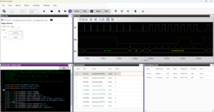
User can write the test script and run the test case from software, which is residing in PC. It will run the test case in real time and offer the result as below
Software allows user write test script and see response from device under test. Also view the timing waveform to debug any timing issues. Software analyses each of I3C protocol packets and reports if there is any error at protocol level.
PGY-I3C-EX-PD has the capabilities to sniff the I3C bus without generating any protocol traffic. This would be useful whenever user want only to monitor the I3C protocol activity in one of the I3C bus.
Challenges faced while testing Multiple I3C bus in DDR5 system
Consider a scenario where a designer has a controller connected to multiple DIMM chips, each equipped with a PMIC and temperature sensor, all linked to a SPD hub. Testing each DIMM individually can be time-consuming, making it highly beneficial to have a solution that allows for simultaneous checking of all DIMMs to streamline the testing process and get data.
Monitoring Simultaneously all I3C bus data: The PGY-LA Multi I3C is a 16-channel logic analyser with 1GS/sec real time sampling rate per channel. Sixteen channels enables the design and test engineers to simultaneously monitor all 8 I3C bus in DDR5 system. This unique capability of simultaneously decoding all eight I3C bus make it a very effective debug and analysis tool for I3C network. It has specially designed to monitor low voltage of 1.0V in DDR5 environment at full 12.5MHz speed.
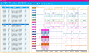
PGY-LA-Multi I3C displays I3C Protocol decoded results in listing window as well as timing waveform for easy
analysis. Timing view supports I3C bus diagram view for each of the I3C bus. By linking protocol data from the listing view to timing view make it convenient to debug the design issues.
Capturing Specific I3C protocol event using hardware based I3C Protocol Event
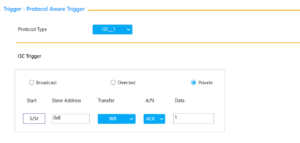
PGY-LA-Multi I3C has a protocol aware trigger capability. User can set the trigger condition based on the I3C Protocol packet content. A protocol-aware trigger is a feature in logic analyser that allows the device to trigger on specific protocol-level events. This means the analyser can be set to start capturing data when a particular sequence of protocol data, such as a specific command, address, or data pattern, occurs on the bus
User can select the I3C bus segment and specify the protocol packet content for trigger. PGY-LA-Multii3C monitor the event in real time and start the capturing the protocol activities.
Conclusion
PGY-I3C-EX-PD and PGY-LA-Multi I3C testing tools forms comprehensive testing solution for design engineers to test the I3C bus. The traffic generation capabilities with powerful scripting to generate different protocol packets at different data rate and errors make it most suitable product to design a I3C devices. While deploying I3C technology at system level design, PGY-LA-Multi I3C 16 Channel Logic Analyzer with ability to simultaneously decode all I3C buses and corelate the data reduces the time to market needs. Please write to us at contact@prodigytechno.com to know more about I3C and I2C Protocol testing solutions


