PCIe and NVMe are two terms that are often heard together. Almost all the latest motherboards support the PCI Express x4 NVMe M.2 drives but may vary from board to board. NVMe is specifically designed to work with the latest solid-state drivers to utilize its full potential. It replaced the AHCI control scheme which also works with SSD but was originally designed to work with old hard drives.

What is PCIe?

Peripheral Component Interconnect Express (PCIe) is a high-performance, general-purpose I/O interconnect or transfer interface defined for a wide variety of future computing and communication platforms. It enables the connection of non-core components such as graphic cards, memory, etc. to the motherboard. PCIe is governed by the PCI-Special Interest Group (PCI-SIG) and it is available at multiple speeds known as different generations. PCIe Gen1, Gen2, Gen3, Gen4 and Gen5 supports 2.5Gbps, 5Gbps, 8Gbps, 16Gbps and 32Gbps speeds respectively. PCIe supports some advanced features such as Power Management, Quality of Service (QoS), Hot-Plug/hot-swap support, data integrity, and error handling.

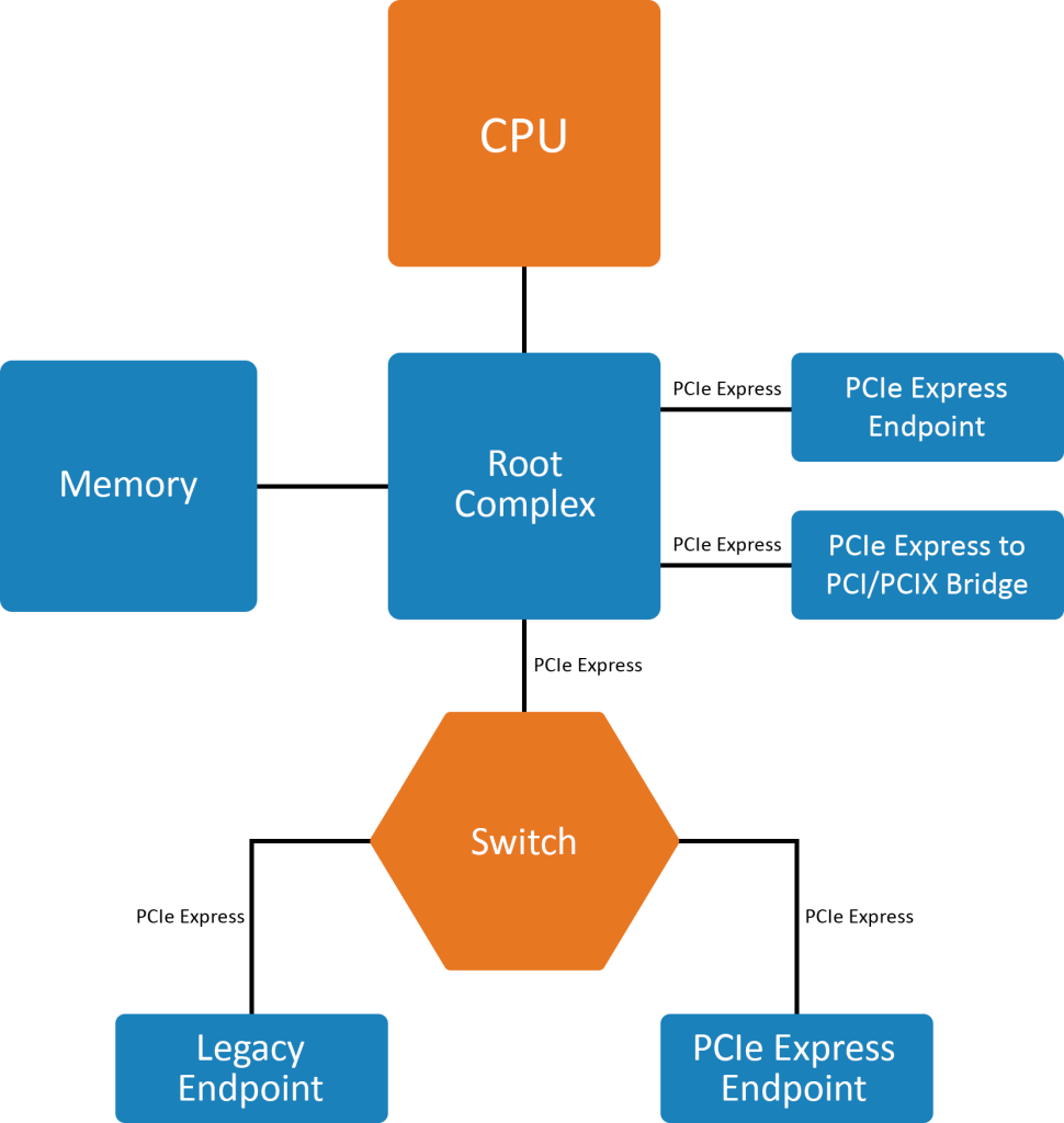
Figure 1- PCIE express example topology

The above figure shows the basic topology of PCIe protocol consisting of a Root Complex (RC), multiple Endpoints (I/O devices), a Switch, and a PCI Express to PCI/PCI-X Bridge. PCIe enables point-to-point connections called links. Each link can support 1 to 32 lanes and each lane consist of 2 pairs of wires, one for transmitting and another for receiving. PCIe implementation can vary depending on the use cases. It can be used to connect ethernet cards, solid-state devices, video cards, and sound cards.

What is NVME?

Non-Volatile Memory Express (NVME) is a transfer protocol that works on top of the transfer interfaces such as PCIe. NVMe is governed by the NVM express work group comprising 90 companies. It defines how a host software communicates with the non-volatile memory over a PCIe bus. It is specially designed for accessing high-speed storage media devices which enables the users to leverage the full potential of SSD technology. NVMe can support up to 64k queues and 64k commands per queue whereas traditional HDDs have 1 queue per command.

Figure 2-classification of NVME transport model

A host and an NVMe sub-system can communicate through 2 constructs – a memory-based transport model and a message-based transport model. The message-based transport model is again classified as a message-only transport model and a message/memory transport model based on how data is transferred between nodes. In the memory-based transport model, the commands, responses, and data are transferred through explicit memory read and write operations. In the message-only transport model data is transferred using capsules or messages and in the message/memory transport model the command capsules, response capsules, and data are transferred in a combination of messages and explicit read or write operations.

Are NVME and PCIE different?

NVMe is a scalable host controller interface designed to work with PCIe-based solid-state drivers. Each NVMe controller is associated with a PCIe function, and it can support multiple namespaces. Namespace is a quantity of non-volatile memory that may be formatted to a logical block, and they are referenced using a namespace id.

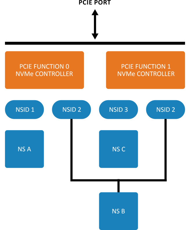
Figure 3 is an example of an NVMe subsystem

with 2 controllers, 2 functions, and a single port. PCIe function 0 is associated with one controller and PCIe function 1 is associated with another NMVe controller. Each controller supports a private namespace and a shared namespace. The namespace id can be the same for the shared namespaces. The controllers sharing a namespace can work concurrently and the ordering requirements while issuing the commands to different controllers are handled by the host software or associated application.

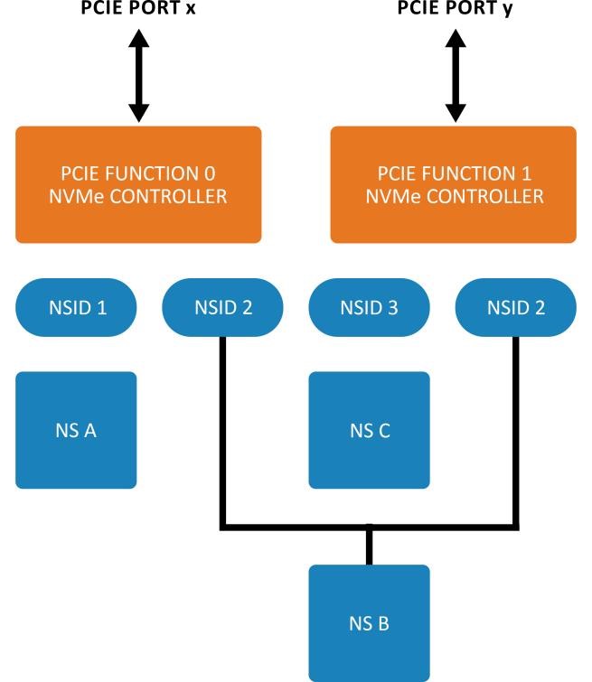
Figure 4 is an example of an NVMe subsystem

with 2 controllers,2 functions, and 2 PCIe ports. The main functionality remains the same as in Figure 3 except the subsystem has 2 ports. These 2 PCIE ports can be of the same root complex or different root complex and may be used to implement both multipath I/O and I/O sharing architecture. The ports are completely independent and have their reset and clock. The reset on one controller will not affect the other controller, its shared namespaces, and the operations performed by the other controller in the shared namespace.

So, PCIe and NVMe are not contradictory technologies rather they both work together to utilize the full capabilities of the latest SSDs. The term PCIE SSD implies how the SSD is connected and NVMe is the format and rules on how the data is stored and accessed.

About the Author:

Anjana Menon is a Technical Lead- FPGA Design at Prodigy Technovations. She graduated from Model Engineering College in 2016 with a Bachelor’s Degree in Electronics & Communication Engineering. She has a Master’s Degree in MTech, Microelectronics from Birla Institute of Technology and Science, Pilani.

Prodigy PCIe Protocol Analyzer

Prodigy’s PCIeGen3/4-PA is a PCIe Protocol Analyzer that supports protocol analysis up to PCIe Gen4 speeds. PCIe design and test engineers can easily capture and record traces at 2.5, 5.0, 8 and 16GT/s at a specific event and obtain error reports instantaneously at an affordable price.

What is Automotive Ethernet?

Automotive Ethernet is designed for in-vehicle communication between the various subsystem of the automobile. Automotive Ethernet is also known as 100 base T1. The subsystem can be connectivity, gateway, ADAS, or the infotainment system.

What is Standard Ethernet?

Standard Ethernet is designed for networking computers and workstations and other devices working on the network. The standard Ethernet is also known as 100 Base TX.

What is the difference between Automotive Ethernet and Ethernet (Automotive Ethernet vs Ethernet)?

1. Automotive Ethernet length is a maximum of 15 meters, due to the harsh environment of the automobile.

2. Automotive Ethernet uses single differential unshielded copper twisted pair, and is lightweight, and costs less to manufacture.

3. Automotive Ethernet connecter type is not defined; Normal Ethernet uses RJ45 connector.

4. PAM-3 signal encoding is used for Automotive Ethernet.

5. 100 Base Tx the maximum length specified is 100 meters.

6. 100 BASE Tx uses a dedicated transmit and receive path.

What are the Protocol Analyzers to Debug Automotive Ethernet?

Prodigy offers a protocol analyzer to capture and monitor Automotive Ethernet. Automotive Ethernet protocol analyzer has advanced capability to allow very long captures which is very useful for the design engineer during the debug.

Introduction

The next-generation cars are growing in complexity by providing advanced features on the infotainment and ADAS sub-systems. The next generation car is more becoming like a data center with subsystems communicating at very speed. Automotive ethernet enables fast  In-vehicle communication to meet the rising demands of the future self-driving and autonomous cars. The term “Automotive Ethernet” can be used to refer to any Ethernet-based network for in-vehicle electrical systems. It includes 100Base-T1 as well as several other variants that are of different speeds and for different purposes. 100BASE-T1 is a 100Mbps automotive ethernet as defined by the IEEE 802.3bp specification.

Benefits

100BASE-T1 automotive ethernet offers higher bandwidth than most of the previous automotive serial data standards. Since it relies on a single, unshielded twisted pair, it also provides a low cost for cabling and reduces the cabling weight by around 30% compared to shielded cabling with connectivity cost savings of up to 80%. 100BASE-T1 also meets the EMC and EMI requirements, as well as the temperature grade requirements required in the automotive application space.

Automotive Ethernet Frame Structure: 

The 100BASE-T1 frame is similar to the traditional ethernet frame but has some slight differences to support the point-to-point topology. One unique aspect of the 100BASE-T1 data frame is that it is marketed by a Start-of-stream delimiter (SSD) and an End-of-stream delimiter (ESD).

The SSD denotes the beginning of the frame. It is always represented by a code group 00,00,00. The code group 00 is reserved especially for the SSD and ESD and is not used anywhere else in data or idle mode. The SSD is followed by the preamble, which in 100BASE-T1 is shortened due to the insertion of the SSD. While the preamble is included, it provides a mechanism for synchronization at the beginning of the frame useful in large networks with a bus connection so that devices could easily synchronize their receiver clocks. But, In 100BASE-T1, It is only present for backward compatibility but not required because of the continuous connection in the point-to-point topology.

The preamble is followed by the Start-of-frame delimiter, or SFD which signifies the end of the preamble and the beginning of the traditional ethernet frame. In conventional Ethernet, the frame starts with a header, including the destination address and the source MAC address, but these are not critical for the 100BASE-T1 due to its point-to-point topology. The header also includes the EtherType field that provides directions on how to interpret the forthcoming data payload.

This is followed by the data payload which is followed by a frame check sequence (FCS), which is a 32-bit CRC used to detect any corruption of data.

The 100BASE-T1 frame ends with the ESD. The ESD can be transmitted in two different ways depending on whether the MII has indicated a tx_error during the data frame. An error-free ESD is represented by a code group 00,00,11. While a frame containing an error will end with 00,00,-1-1. Like the SSD these specific sequences are reserved for such purposes.

After the ESD, Idle symbols are again transmitted. The presence of the ESD in 100BASE-T1 shortens the interframe gap (IFG).

100ASE-T1 Frame format

Figure 4. 100ASE-T1 Frame format

 A 100BASE-T1 packet consisting of SSD and ESD denoted using red bars at edges

Figure 5. A 100BASE-T1 packet consisting of SSD and ESD denoted using red bars at the edges

00BASE-T1 packet consisting of MAC address as in legacy Ethernet

Figure 6. Following the Preamble and SFD the frame begins with the header that contains the MAC address as in legacy Ethernet. These are not necessarily required in point-to-point topology but are reserved to maintain backward compatibility.

Automotive Ethernet Theory of Operation:

100BASE-T1 uses a point-to-point topology directly connecting two nodes. The ‘-T1″ signifies that the signal is carried over a twisted pair of cables which in this case is an unshielded twisted pair. Unlike conventional ethernet types like 100BASE-Tx, 100BASE-T1 is a full duplex signal. Hence, the same pair will carry a bidirectional signal from a master to the slave. If this signal were to be observed using an oscilloscope alone it would not be possible to recognize which signal is from the master and which is from the slave, since both signals are transmitted simultaneously. A directional coupler is one solution to this and the other approach would be to decode traffic from one DUT independent of the other.

100BASE-T1 Physical Topology

Figure 1. 100BASE-T1 Physical Topology

Automotive Ethernet Signaling:

100BASE-T1 uses PAM3 signaling. PAM stands for Pulse Amplitude Modulation and it uses the amplitude of the signal to encode the message information. PAM3 uses three distinct levels. The receiver sets a high and low threshold to determine the levels. Any samples above the high level are a +1 and a -1 below the low level and a 0 between the two levels. Signaling with three distinct values like in PAM3 is called a ternary signal or in the case of Automotive Ethernet a ternary symbol. In 100BASE-T1, two ternary symbols are combined to form a code group. When a code group is representing data, it represents 3 bits of data. The 100BASE-T1 specification defines how these code groups are mapped to the 3 bits.

PAM3 Signaling

Figure 2. PAM3 Signaling

Automotive Ethernet Link Startup and Handshake

Upon power-up, The master and slave initiate a handshaking process to establish the link, called the link startup or link training process. The link startup uses three different signals

  • SEND_Z – Denotes the transmission of all zeroes, called zero codes.
  • SEND_I – Denotes the transmission of PAM3 idle signals.
  • SEND_N – Denotes the transmission of PAM3 data or idle signals.

The handshake between the master and the slave will progress through these three types of signals. The link startup begins with the master transmitting PAM3 idle signals as it transitions from SEND_Z to SEND_I. During this time the slave continues to transmit SEND_Z. This allows the master to train its echo canceller, while the slave synchronizes to the master’s clock, locks its scrambler, and adjusts its signal conditioning.

 100BASE-T1 Link Startup

Figure 3. 100BASE-T1 Link Startup

In the above image, we can notice the 100BASE-T1 link startup showing the master in yellow and pink and the slave in blue and green switching from SEND_Z to SEND_I and SEND_N.

After this, the slave switches from SEND_Z to SEND_I while the master is still in SEND_I. This allows the slave to train its echo canceller, while the master locks its scrambler and adjusts the signal conditioning. The master and slave continue to send idle symbols (SEND_I) while they refine the timing, equalizer, and scrambler.

The last step is for the master and slave to validate that the link startup was successful by setting the scr_status, loc_rcvr_status, and rem_rcvr status. If these statuses are all validated, both the master and slave switch to the SEND_N state. If any of the above-mentioned statuses fail, the link startup restarts. The below image shows the completion of the link startup and the exchange of scrambler status messages.

Link startup completion

Figure 4. Link startup completion

Debugging Automotive Ethernet :

Debugging automotive ethernet remains a challenge. The engineer needs to understand the lower-level signaling as well the packet information. Prodigy Technovations provides an advanced protocol analyzer to debug automotive ethernet devices or interfaces with the ability to capture long-duration of packets.

Prodigy’s 100BASE-T1 Automotive Ethernet Protocol Analyzer

Check out – Prodigy’s 100BASE-T1 Automotive Ethernet Protocol Analyzer

Other Protocol Analyzers

How to test the I3C devices for Interoperability or Conformance Testing?

I3C Protocol is gaining momentum and going to be mainstream technology in automotive, data centers, and many other applications. The number of semiconductors with I3C interfaces shipped in the market has grown 3x in the last 3 years the growth is expected to double in the coming decade. With the growth in semiconductor chips having I3C interfaces the devices such as sensors and eeproms also need to support or migrate towards I3C Protocol. Migration to the I3C interface will enable devices to send higher performance and better control and configuration.

Here are some of the main advantages of migration to the I3C Interface

  • Multi-master support and Multidrop capability
  • Dynamic addressing
  • In-band interrupts
  • Hot Join support of new devices

However, migration to I3C Interface is a good option but comes with some obstacles as well. The I3C devices need to work with each other as during the migration some devices will support I3C Interface and others will continue to use the legacy I2C Interface.

MIPI consortium which has defined the I3C Specification has recently come up with the standard for Interoperability testing of I3C devices.

The test suite has the following details.

1. There is a total of 55 tests defined in various categories and in that some tests have subtests.

2. Target Dynamic address assignment tests cases to test dynamic address-related commands. These tests verify that the target detects and correctly implements commands. These tests are crucial to a target to operate on an I3C bus.

How to run I3C Interoperability tests on your I3C device:

Prodigy Technovations has come up with an I3C Protocol conformance test suite to enable interoperability testing of I3C devices. It’s a simple test suite run along with I3C PGY Device. Once the tests are run the device manufacturers will be easily able to find any conformance issues related to I3C Protocol. The test suite empowers engineers and saves a significant amount of development time and gives confidence in the I3C device.

Request For Quote

Share your requirement and our team will provide a tailored quote based on your validation needs.

"*" indicates required fields

This field is for validation purposes and should be left unchanged.
Address*

Request For Demo

Tell us your use case and our team will schedule a product demo aligned to your validation workflow.

"*" indicates required fields

This field is for validation purposes and should be left unchanged.
Address*

Request A Demo

Tell us your use case and our team will schedule a product demo aligned to your validation workflow.

"*" indicates required fields

This field is for validation purposes and should be left unchanged.
This field is hidden when viewing the form
Address*

Request Quote

Share your requirement and our team will provide a tailored quote based on your validation needs.

"*" indicates required fields

This field is for validation purposes and should be left unchanged.
Address*