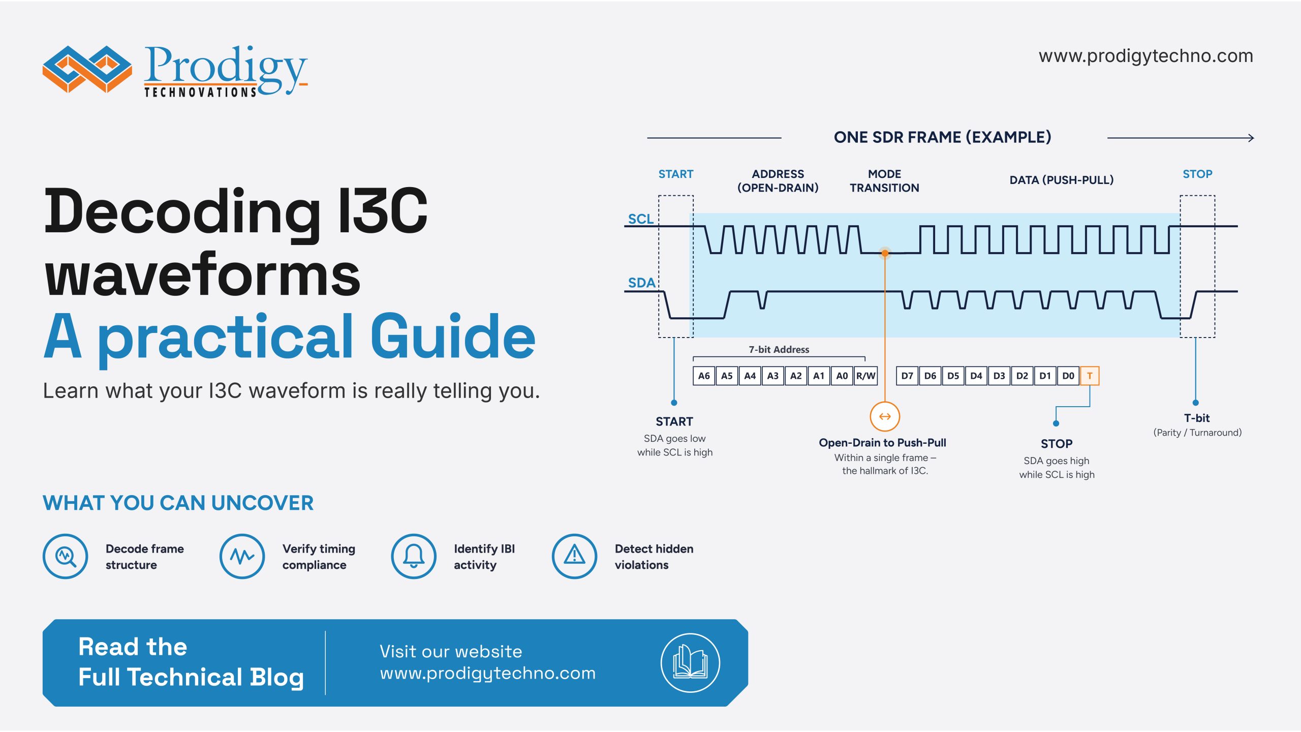
Two wires. That is all I3C gives you. Two wires carrying a clock and a data stream, the same physical interface engineers have been probing since I2C arrived in 1982. Open a capture and the waveform looks familiar. The muscle memory from a decade of I2C debug kicks in before the conscious mind catches up.
That familiarity is the trap.
On those same two wires, I3C protocol does a lot. It runs multiple signaling modes, manages dynamic device discovery, and handles target-initiated interrupts. That too at speeds where a two-nanosecond timing violation leaves no waveform.
Reading an I3C waveform correctly is not about having better eyes. It is about knowing what the waveform is actually telling you, layer by layer, and knowing what it is hiding.
This article walks through both.
Anatomy of a healthy I3C capture
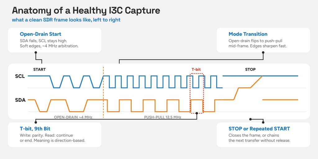
A healthy I3C waveform looks almost familiar, START condition, address, data bytes, and STOP. Here’s what a clean SDR frame looks like, left to right.
START: SDA pulls low while SCL is high. Identical to I2C. This is where the similarity ends.
Address header – open-drain phase: SDA rises passively through the controller’s integrated pull-up. Edges are soft, rise times slow, clock rate around 4 MHz. Multiple devices may be contending for the bus. Open-drain is the only safe way to arbitrate.
Mid-frame mode transition: After the address gets resolved, the bus switches to push-pull. SCL climbs to 12.5 MHz, SDA transitions sharpen into the sub-nanosecond range. The waveform visibly tightens. This transition, open-drain to push-pull inside a single frame, is the clearest visual signature that you are looking at I3C and not I2C. Unlike I2C, I3C clock stretching is not allowed. The controller owns SCL completely, which is why timing violations at the controller level have no built-in recovery mechanism.
Data bytes: Each nine bits wide. The ninth is the T-bit, and its meaning is context-dependent.
- Controller writes: odd parity over the preceding eight bits
- Controller reads: 0 = continue, 1 = end of transfer
A decoder that doesn’t track transaction direction can misread T-bits. And those misreads cause phantom protocol errors downstream.
STOP or Repeated START: Closes the frame or chains the next transaction without releasing the bus.
Every anomaly you’ll encounter in a real capture is a deviation from this structure.
Reading a mixed-bus capture: I3C and I2C on the same two wires
A mixed-bus capture looks like one continuous stream of traffic. I3C targets and legacy I2C devices sharing the same two lines, nothing labeling which frame belongs to which protocol. There are three tells that make it readable.
- SCL duty cycle
I2C has a 50% duty cycle, equal time high and low.
I3C in push-pull mode is asymmetric. The SCL high period is capped at 40 ns, deliberately shorter than the 50 ns glitch filter mandatory in every I2C device. Any pulse below that threshold is invisible to I2C silicon.
On a scope, a narrow, high pulse and then a longer low period is I3C. A balanced one is of I2C.
- The ninth bit
The ninth clock pulse exists in both protocols, but the information carried on SDA is different. In I2C, the ninth bit is always an ACK or NACK. In I3C, the ninth bit is a T-bit whose interpretation depends on the direction of the transaction.
- Rise time
I2C uses open-drain signaling end-to-end. So, SDA rises passively through a pull-up resistor. And produces relatively slow, rounded edges. In contrast, I3C drives SDA actively in both directions during push-pull operation, resulting in much sharper transitions.
One additional landmark is broadcast address 0x7E. A START followed by 0x7E means the controller is issuing a Common Command Code to all I3C devices. Legacy I2C devices will not respond. Activity from an I2C address after a 0x7E broadcast is a configuration problem.
Timing parameters: the numbers that matter and why
Reading a capture at the frame level tells you what the bus is doing. Reading it at the timing level tells you if it’s done correctly. On I3C buses, these are different questions. Dual-mode signaling means timing requirements change mid-transaction, and a parameter legal in the open-drain phase can be a violation in push-pull.
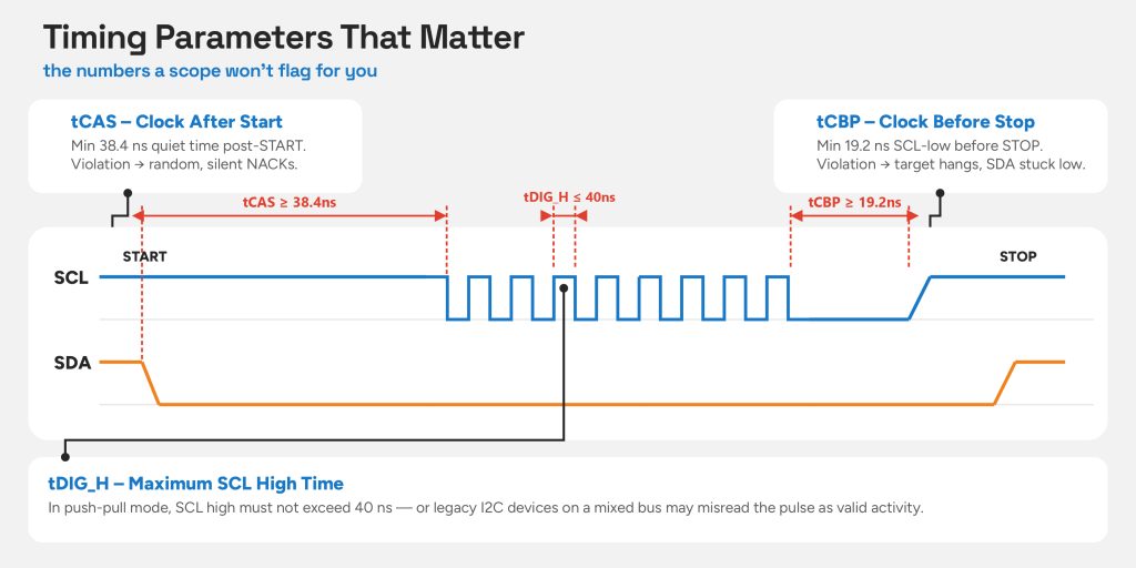
- tCAS: Clock After Start
The minimum quiet time after a START before SCL begins toggling. A guard interval that gives every device time to recognize the START and prepare its state machine.
In push-pull SDR mode, the MIPI I3C Basic spec sets tCAS minimum at 38.4 ns. At 12.5 MHz that is less than half a clock period. Violations leave no visual artifact, but a target with a setup time close to the minimum will intermittently fail to recognize the START.
The failure surfaces as a random NACK with no apparent physical cause. Without automatic spec-table flagging, this class of bug is nearly impossible to find by eye.
- tCBP: Clock Before Stop
The trailing-edge counterpart to tCBP. Before asserting a STOP, SCL must be held low for a minimum of 19.2 ns, giving targets enough time to recognize the STOP is coming and release the bus cleanly. Cut that window short and targets miss it entirely, locking in their current state: SDA held low, bus blocked, device appearing to hang.
- tDIG_H: maximum SCL high time
In push-pull mode, SCL high shouldn’t cross 40 ns. Otherwise, legacy I2C devices may interpret I3C traffic as valid bus activity.
In a mixed-bus capture, a tDIG_H violation appears as unexpected activity from an I2C address, a silent device suddenly driving SDA. The root cause is a pulse that ran a few nanoseconds too long. The symptom looks like a misbehaving I2C device.
HDR mode: When the waveform changes shape
HDR mode is where a patient eye and a good oscilloscope stop being enough. The waveform changes character so completely that engineers encountering it for the first time assume something is wrong with their capture setup. In reality, the bus just shifts into a different encoding scheme.
The transition begins in SDR. The controller broadcasts to 0x7E and issues an ENTHDR CCC, the mode gate. Everything before it follows SDR rules. Everything after follows HDR rules. A decoder that doesn’t recognize this boundary applies SDR interpretation to HDR frames and produces what looks like catastrophic bus corruption.
HDR-DDR is the most common implementation and the most immediately visible. Data is sampled on both the rising and falling edges of SCL, doubling the amount of data transferred per clock cycle. Each frame consists of a 2-bit preamble, a 16-bit payload, and 2 parity bits, for a total of 20 bits transmitted over 10 clock pulses.
Because data is valid on both clock edges, SDA appears to toggle at twice the expected rate. Without DDR-aware decoding, this can be mistaken for a signal-integrity issue.
HDR-TSP and TSL go further. They abandon the clock-and-data relationship entirely. Both SCL and SDA carry data simultaneously through three defined transition symbols. There is no steady clock to lock onto. On a scope without ternary-aware decode, it is indistinguishable from noise.
Waveform anomalies: What goes wrong and what it signals
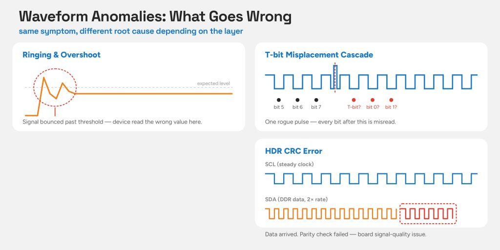
The same symptom at the protocol layer can have completely different causes depending on where in the stack the problem originates. Four common patterns worth knowing include:
- Ringing and overshoot
The move to push-pull signaling brings much steeper edges. Those edges can excite parasitic elements on the board. And create brief overshoot events. Although short-lived, they can still cause decoding errors if they coincide with the receiver’s sampling point.
- T-bit misplacement cascade
The effect of an SCL glitch isn’t just confined to a single bit. If the target loses count, every boundary after that shifts by one position. What, ideally, should be thought of as data becomes a T-bit, and vice versa.
- HDR CRC errors
Individual frames fail their parity check inside an otherwise clean HDR session. The mode entry is correct, the framing is correct, but data is corrupted. This is almost always a signal integrity problem, as HDR-DDR’s faster edges are more sensitive to board impedance issues than SDR.
What a professional analyzer shows that a scope misses
A generic oscilloscope with I3C decode can show you frames. What it cannot do is maintain protocol state across a capture. Every frame is read in isolation. The T-bit on byte seven of a read transaction requires the decoder to have tracked transaction direction from the opening address frame through every preceding byte. A stateless decoder guesses, and on a bus running HDR sessions, IBI interjections, and mixed I2C traffic simultaneously, guessing produces a protocol view that looks plausible and is partially wrong. That is the worst possible outcome. It gives you false confidence.
Timing violations compound the problem. A tCAS violation at 36 ns, two nanoseconds below minimum, leaves no waveform artifact. Finding it manually requires cursor measurements on every START in the capture.
The PGY-I3C-EX-PD from Prodigy Technovations tackles exactly this. It functions simultaneously as a protocol analyzer and a bus exerciser.
As an analyzer, it decodes SDR, HDR-DDR, TSL, and TSP traffic in a single capture. The I3C timing diagram view overlays decoded protocol bits directly onto SCL and SDA waveforms, with auto-correlation between the protocol listing window and the timing plot. Clicking any packet jumps the waveform view to that exact transaction. Error detection covers S0 through S5 error types as defined in the I3C specification, CRC errors in DDR traffic, preamble errors, ACK/NACK failures, and non-standard start, stop, and HDR exit patterns. Nothing requires manual hunting.
As an exerciser, it can be configured as an I3C controller, secondary controller, or up to three targets simultaneously, allowing engineers to replace either side of a suspected fault with a known-good reference.
The limiting factor in I3C debug is rarely signal quality. It is decode intelligence. A clean waveform with a protocol violation inside it looks identical to a clean waveform without one, unless the tool understands the I3C decoding well enough to know the difference.