MCTP standardizes how management messages are structured and addressed. I3C provides the physical transport that carries them. When they’re combined, engineers deal with two initialization sequences, two addressing schemes, and failure modes that span both layers simultaneously.
And when something goes wrong, the symptom at the top gives you almost nothing to work with. A command that never gets a response could be a DAA failure, a missing endpoint ID, a dropped packet, or an application-layer rejection. Knowing which one requires understanding exactly how the two protocols interact and where each layer is most likely to break. Here, we’ll cover how MCTP uses I3C as its transport layer, what debugging challenges you might run into, and what you can do about them.
Why MCTP Uses I3C as a Transport Layer?
Modern servers come with multiple components that need to be actively managed like SSDs, power controllers, temperature sensors, accelerators, and memory modules. Each of these needs to report health status, accept firmware updates, respond to configuration commands, and raise alerts during emergencies. MCTP, defined by the DMTF, is the protocol that standardizes how these management messages are structured and addressed. But MCTP is only the messaging system. It doesn’t define the physical wires or the electrical signals that carry those messages. That’s the job of the transport layer. And MCTP is designed to work over several of them, including PCIe, SMBus, and I3C.
Why not just use SMBus?
SMBus has been the default transport layer for over two decades. But it has real limitations.
It runs at 1 MHz. It uses static addresses. It requires separate interrupt lines for each device. And as servers grow more complex, SMBus only creates more problems. I3C removes most of these constraints. It runs at 12.5 MHz, uses dynamic address assignment, supports in-band interrupts without extra wires, and consumes significantly less power. The binding that defines how MCTP uses I3C as its transport layer is DMTF DSP0233, the MCTP I3C Transport Binding Specification. It specifies exactly how MCTP messages are packaged and carried over an I3C bus.
How Communication Happens in an MCTP-over-I3C System?
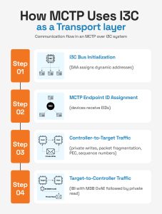
MCTP over I3C follows a strict sequence. The I3C bus must be fully initialized before any MCTP traffic can flow.
Step 1: I3C Bus Initialization
DAA completes first. Every MCTP-capable device gets a dynamic I3C address. MCTP devices are identifiable during DAA by their DCR value of 0xCC, the MIPI-assigned Device Characteristics Register value for MCTP endpoints.
Step 2: MCTP Endpoint ID Assignment
Post DAA, all the devices get an MCTP Endpoint ID (EID) through the MCTP bus initialization sequence. The I3C address routes the message to the right device. The EID identifies the MCTP endpoint within it. Both are required.
Step 3: Controller-to-Target Traffic
The controller sends MCTP messages as I3C private writes. Large messages have to be broken down as the baseline MTU is 69 bytes with 64 bytes of payload, a 4-byte MCTP header, and 1 PEC byte.
Each packet has:
- Sequence numbers
- Start-of-Message / End-of-Message flags
- A PEC byte for CRC-8 error detection
Step 4: Target-to-Controller Traffic
When a target has data ready, it raises an IBI using the MIPI-defined MDB value of 0xAE for MCTP traffic. The controller acknowledges the interrupt and performs a private read to retrieve the packet. If IBIs are not enabled, the controller falls back to polling with GETSTATUS.
What Can Go Wrong?
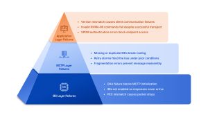
Failures in an MCTP-over-I3C system fall across three layers.
I3C Layer Failures
- DAA failure: MCTP endpoint discovery can’t begin until every device has a valid dynamic address. A DAA failure blocks the entire MCTP initialization sequence before it starts.
- IBI not enabled: If the controller hasn’t issued ENEC to enable IBIs, targets can’t notify the controller of pending data. The target raises an IBI with MDB = 0xAE, the controller ignores it, and the response never arrives.
- PEC mismatch: Every MCTP packet over I3C includes a CRC-8 PEC byte. A signal integrity issue that corrupts even a single bit causes a PEC failure and the packet is discarded. Under intermittent signal conditions, this appears as random message loss.
2. MCTP Layer Failures
- EID assignment failure: I3C dynamic addresses and MCTP Endpoint IDs are independent. A device can have a valid I3C address and still have no EID, or a duplicate EID, if MCTP bus initialization didn’t complete correctly. Messages routed to an unassigned or duplicate EID either go nowhere or reach the wrong endpoint.
- Timeout and retry storms: DSP0233 has clear timing requirements for MCTP control messages and data transfers. When a response takes too long, the sender retries the transaction. Under poor bus conditions, repeated retries can quickly increase bus traffic and make the original problem quite difficult to diagnose.
- Fragmentation and reassembly errors: Large MCTP messages are divided into different packets when they’re more than the negotiated MTU. If even one packet goes missing, arrives out of order, or carries the wrong sequence number, the receiver may fail to rebuild the message correctly.
3. Application Layer Failures
- Version mismatch: NVMe-MI, SPDM, and PLDM each have versioned specifications. A controller and endpoint running incompatible versions will reject each other’s messages, often silently, with no clear error at the transport layer.
- NVMe-MI command rejection: A correctly delivered MCTP packet can also fail at the NVMe-MI layer. The command might be malformed and unsupported. Or sent while the controller is in an unexpected state. When that happens, the transport path works correctly, but the application-level transaction still fails.
- SPDM authentication failure: In case the certificate exchange fails, times out, or uses mismatched algorithms, the endpoint might get marked as untrusted and blocked from further communication. This presents as a connection failure at the application layer with no visible I3C or MCTP error.
Why These Failures Are Difficult to Debug?
The layered architecture that makes MCTP over I3C powerful is the same reason it’s hard to debug.
An NVMe-MI command that never gets a response could be a DAA failure, a missing EID, a dropped packet, a PEC error, or an application-level rejection. The symptom is identical across all of them. The layer where it actually broke down is not visible from the top.
Reasons why I3C-MCTP debug can be difficult include:
- Starting at the wrong layer: Most engineers start debugging at the layer where the symptom appears. An NVMe-MI timeout gets debugged as an NVMe-MI problem when the actual cause is a PEC mismatch two layers down. Without visibility across all three layers at once, finding the root cause means working through each possibility manually.
- Failures that rarely appear in the lab: Issues like intermittent PEC errors or fragmentation problems in heavy traffic occur only during sustained transfers or power state transitions. It’s quite difficult to pinpoint these problems because of their unpredictable occurrence that often falls outside short trace windows.
- Failures with no signal at the bus level: An SPDM version mismatch or an unsupported NVMe-MI command produces no error at the I3C or MCTP layer. The packet was delivered correctly. Without an application-layer protocol decode, there is nothing to see.
How Protocol Analyzers and Exercisers Can Help?
Debugging MCTP over I3C effectively requires visibility across all three layers at the same time, the I3C, MCTP, and the application protocol. A general-purpose logic analyzer or oscilloscope covers the physical layer. It doesn’t decode MCTP packets, reassemble fragmented messages, or flag an SPDM version mismatch. That requires a purpose-built tool.
What an analyzer needs to do
The analyzer has to decode the full stack in a one correlated view:
- At the I3C layer, the DAA sequence, IBI events, PEC errors, and timing violations
- At the MCTP layer, the endpoint addressing, packet fragmentation and reassembly, sequence number tracking, and error detection
- At the application layer, the NVMe-MI commands and responses, SPDM handshake sequences, and PLDM message exchanges
What an exerciser adds
An exerciser lets engineers isolate failures by replacing one side of the system with a known-good reference. If NVMe-MI commands aren’t getting responses, replacing the controller with an exerciser and replaying the same command sequence immediately answers whether the problem is in the controller or the endpoint. The same approach works in reverse for testing controllers against a known-good target.
Prodigy Technovations’ PGY-I3C-EX-PD combines both in a single platform. It decodes MCTP over I3C including message type identification, endpoint addressing, multi-packet reassembly, and error detection.
At the application layer, it decodes NVMe-MI commands and responses, full SPDM handshake sequences, and PLDM message exchanges. All displayed in a correlated protocol listing view alongside the I3C timing diagram.
As exerciser, it can generate scripted MCTP traffic. That way, controlled command sequences can easily be sent to the DUT and the response can be observed across protocol layers.
The platform also supports error injection, including PEC faults and IBI NACK scenarios, so teams can test error handling under controlled conditions instead of waiting for rare failures in the field.
In short, the right platform makes every layer visible at once. And cuts the time from symptom to root cause significantly. Learn more about how the PGY-I3C-EX-PD approaches MCTP over I3C validation.