UFS is becoming widely used storage device in many different applications smartphone, Tablets, Digital Cameras and Camcorders, Automotive, Augmented Reality and Virtual reality, wearable, augmented devices and hard disk drives. Now it expected to used in laptops in the near future.

UFS stands for Universal Flash Storage. It is type of non-volatile memory which can have a storage capacity of 1TB. This technology is adopted and deployed many leading companies such as Qualcomm, Intel, MediaTek, Kioxia, Samsung, Wester Digital, Micron, Silicon Motion and many more companies.   This standard is developed and maintained by JEDEC Solid State technology Association and MIPI alliance . UFS devices are gradually replacing eMMC, SD card and even SSD applications. UFS technology used in many more applications which needs low latency, high speed data transfer and low power consumption. Latest UFS standard is UFS4.0, each lane operates maximum data rate of 23.32Gbps.  UFS is based on SCSI architecture and supports SCSI tagged command queuing.

UFS is uses the MPHY for physical layer and UniPro for datalink and transport layer of the protocol. Both MPHY and UniPro Standard is developed and maintained by MIPI Alliance. UFS is available in UFS2.0, UFS2.1, UFS3.0, UFS3.1 and UFS4.0 versions. The main difference between these versions of the UFS standard is data rate and high-performance booster commands.

UFS Protocol is encapsulated in Unipro layer. To understand UFS protocol , we have to know focus on three  layers of OSI

  1. Physical Layer known as MPHY
  2. Datalink and Transport layer is UniPro
  3. Application layer is UFS

Host and Device are interfaced using physical layer MPHY. Host manages the read and write operation of UFS device. UFS controller within the manages NAND memory (Flash) with the UFS device.

Data Link layer  manages the data transfer between the host and device and vice versa. Dat flow control ensures that data is delivered to the host or device by monitoring the CRC value of the data.

Physical layer manages the encoding of the data, scrambling and packetizing the data received from UniPro layer through the RMMI interface over to host or device using LVDS lines.  Advanced power management system in MPHY allows users to program the device to place in hibernate, sleep state, use one or two lane data transmission in different modes.

MCTP Over I3C in the PGY-I3C-EX-PD

Overview of I3C

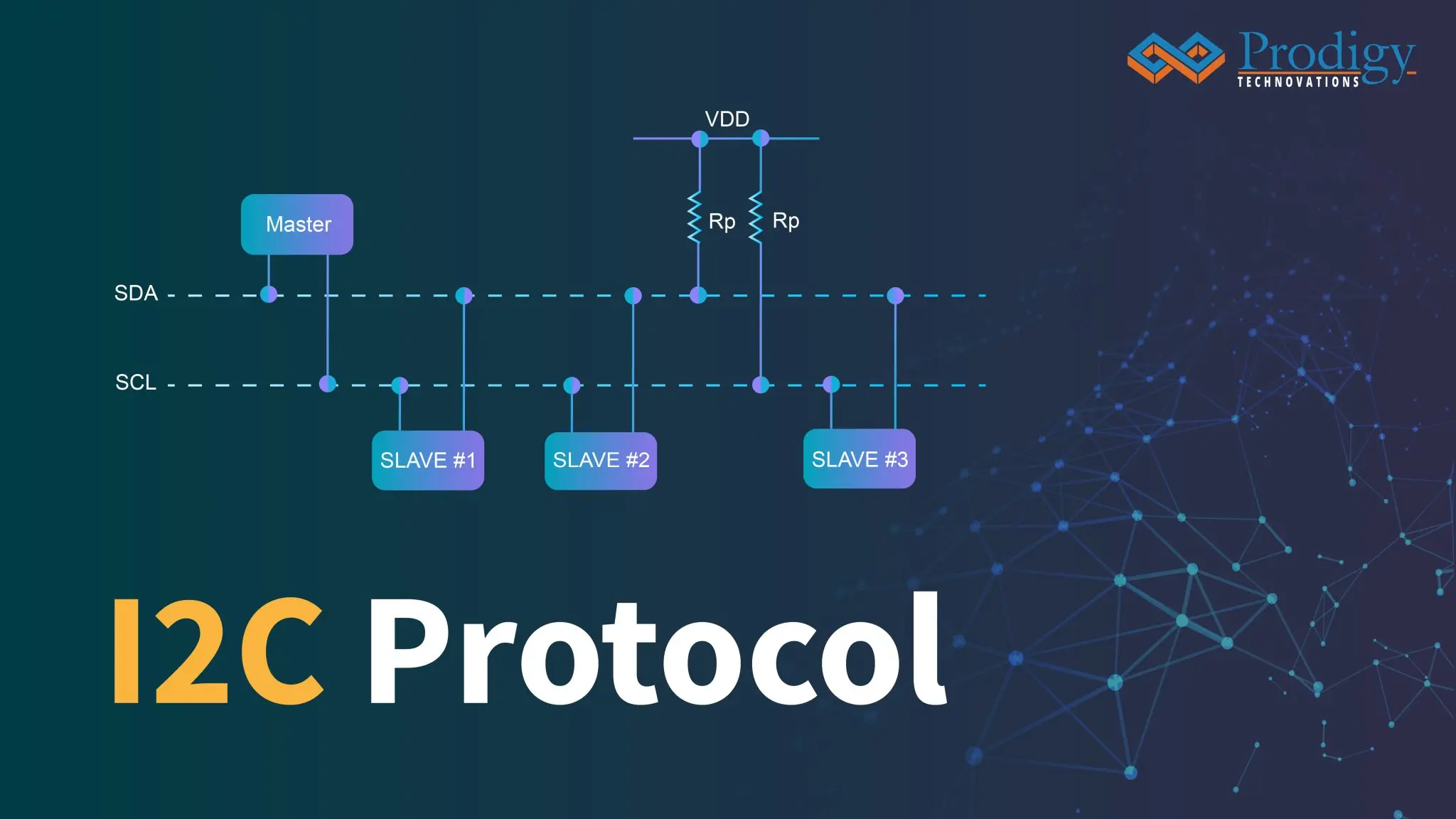
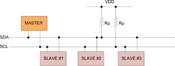
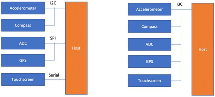
MIPI I3C, or I3C, stands for the MIPI I3C (Sensor Interface) standard, which serves as a versatile and efficient interface for connecting sensors to application processors, microcontrollers, and other intelligent devices. I3C is designed to overcome limitations of traditional sensor interfaces like I2C and SPI by offering improved data throughput, lower power consumption, and additional features such as dynamic addressing and in-band interrupts. It combines the best aspects of both I2C and SPI while introducing innovations tailored to the demands of modern embedded systems. I3C facilitates streamlined communication between sensors and host devices, providing a scalable and standardized solution that enhances interoperability and flexibility in a wide range of applications, from smartphones and IoT devices to automotive and industrial systems.

system_overview of I3C_Interface_prodigy_technovations

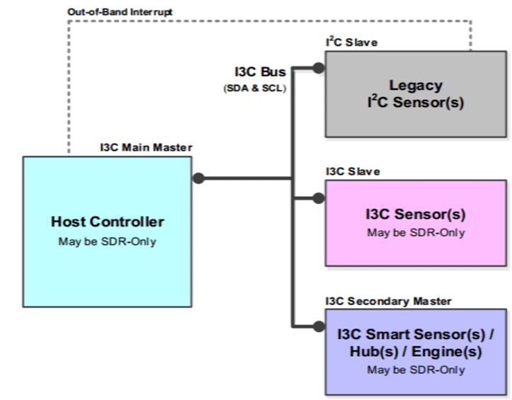
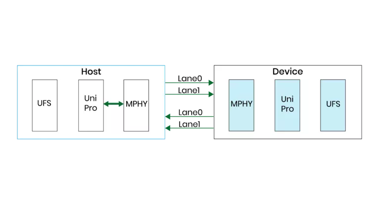
Figure 1: System Overview of I3C Interface

Overview about MCTP:

The MCTP, or Management Component Transport Protocol, is a communication protocol that facilitates communication between management controllers, components, and intelligent platforms. It is commonly used in system management and platform management applications, providing a standardized approach for managing devices in a distributed computing environment.

physical_topology_I3C_bus_MCTP_prodigy_technovations

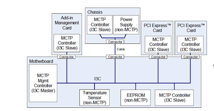
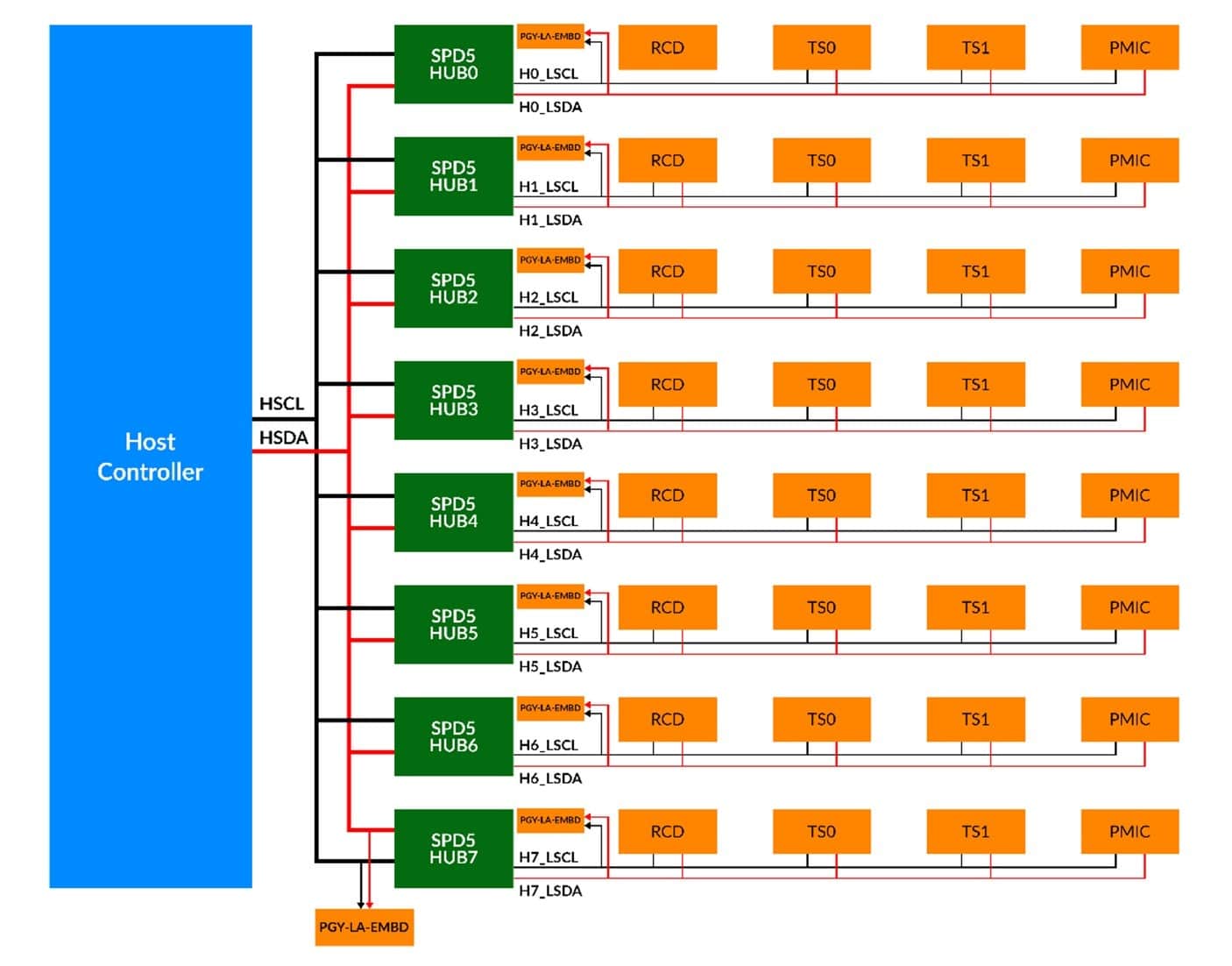
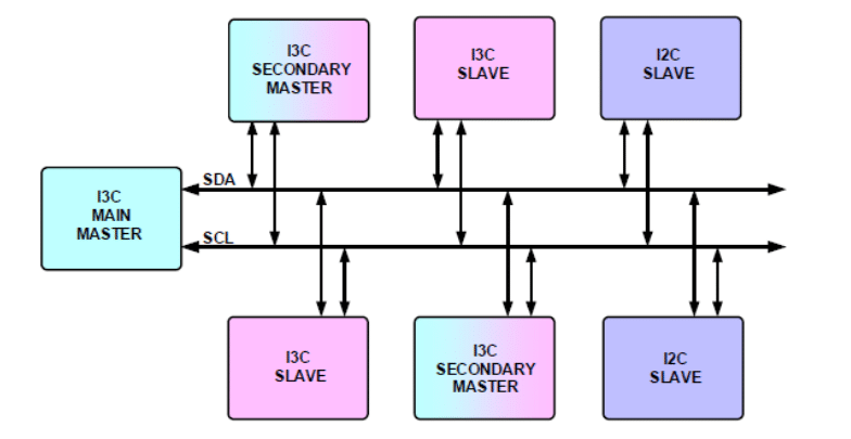
Figure 2: Physical Topology of I3C bus in the MCTP

It serves as a standardized and interoperable solution for communication between management controllers, components, and intelligent platforms. MCTP enables efficient and secure interactions, facilitating tasks such as configuration, monitoring, and control of hardware components in a system. With a focus on scalability and flexibility, MCTP is widely used in diverse applications, including data centers, cloud computing, and embedded systems. It provides a framework for managing the lifecycle of components, ensuring seamless integration and communication across various hardware elements within a computing environment.

MCTP in I3C:

The integration of MCTP with I3C leverages the advantages of both protocols. I3C serves as the physical layer for MCTP, offering a reliable and efficient communication medium for management and control purposes. MCTP messages are encapsulated within I3C frames, enabling seamless communication between management entities while benefiting from the unique features of I3C.

MCTP (Management Component Transport Protocol) in I3C (MIPI I3C) signifies the integration of MCTP as a management and control protocol within the framework of the I3C standard. In this context, I3C serves as the physical layer for MCTP, providing a reliable and efficient communication medium for managing devices in distributed computing environments. The combination of MCTP and I3C allows for seamless communication between management controllers, components, and intelligent platforms. MCTP messages are encapsulated within I3C frames, leveraging the unique capabilities of I3C such as dynamic addressing and in-band interrupts. This integration enhances the overall efficiency and manageability of devices, enabling standardized communication for configuration, monitoring, and control purposes in systems adopting both MCTP and I3C protocols. The use of I3C as the underlying transport layer for MCTP contributes to a more streamlined and interoperable approach to managing components within a computing system.

Challenges in Decoding MCTP:

Implementing MCTP decoding capabilities within an I3C interface presents several challenges that need to be addressed for successful communication and interoperability:

  1. Complex Message Structure: MCTP messages can have a complex structure with multiple layers of encapsulation. Decoding these messages requires a deep understanding of the MCTP protocol and the ability to parse nested structures accurately.
  2. Error Handling: Ensuring robust error handling is crucial, especially in dynamic and distributed environments. Properly managing error conditions, such as corrupted messages or protocol violations, is essential for maintaining the reliability of the communication link.
  3. Compliance with Specifications: MCTP specifications may evolve, and ensuring compliance with the latest standards is vital for compatibility with other devices and systems. Regular updates to the decoding capabilities may be required to support new features and enhancements introduced in the MCTP standard.
  4. Performance Optimization: Efficient decoding is essential for real-time applications. Balancing the need for comprehensive decoding with optimized performance is a key consideration, particularly in resource-constrained environments.
  5. Interoperability Testing: Ensuring interoperability with a diverse range of devices implementing MCTP over I3C is critical. Rigorous testing against different MCTP implementations helps identify and resolve compatibility issues, ensuring seamless communication in various deployment scenarios.

By addressing these challenges, developers can implement robust MCTP decoding capabilities within an I3C interface, enabling reliable communication and effective management of devices in intelligent platforms.

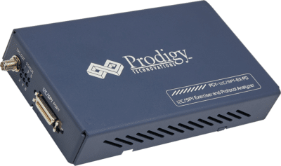
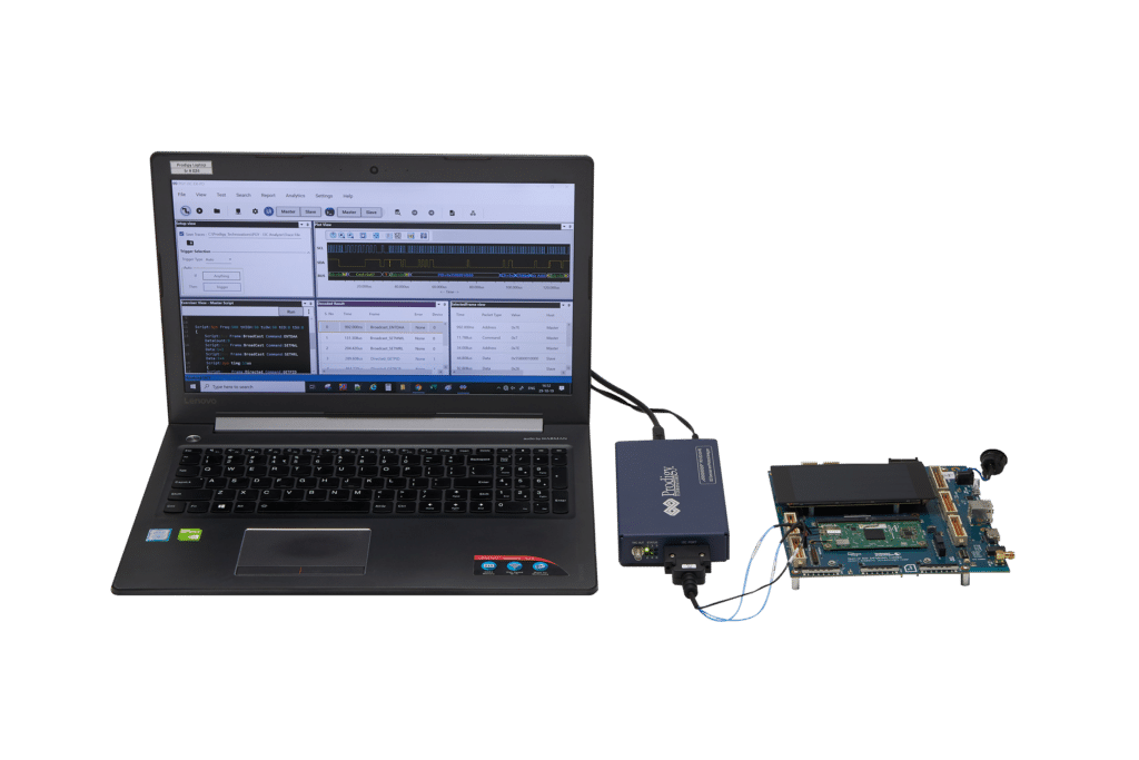
How does the PGY-I3C-Exerciser and Protocol Analyzer help in decoding the MCTP protocol packets?

Exerciser Mode:

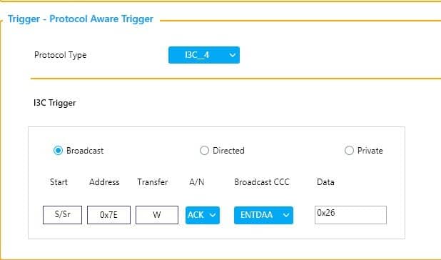
Within the settings menu of the Analyzer, users can opt for ‘Support for MCTP,’ a feature akin to triggering the emulating and decoding capture process of MCTP traffic. Following this selection, users can configure both the controller and target and later emulate the MCTP traffic by sending MCTP commands from the software.

When utilized in exerciser mode, the PGY-I3C-EX-PD grants users the flexibility to configure it either as a controller or target. Subsequently, it can emulate MCTP traffic and decode the results.

Initialization of MCTP Protocol:

(Here Controller is referred to as Primary and Target is referred as Secondary)

Case-1Transmission of MCTP packets from the Primary to the Secondary

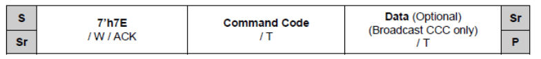
This happens using Primary-initiated private write transfer as defined in Specification for I3C Basics. The transfer shall be directed to the Target I3C address used for MCTP protocol communication.

MCTP_over_I3C_packet_transfer_format_primary_secondary

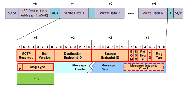
 Figure 3:MCTP over I3C packet transfer format: Primary to Secondary

The PGY-I3C-EX-PD facilitates this scenario through the configuration of both the controller and target, initiating the Private Write Transfer from the controller using MCTP commands.

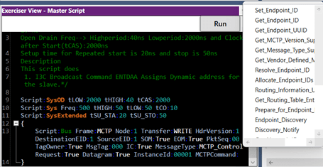
Figure 4: MCTP Supported Commands

MCTP_primary_to_Secondary_transactions_prodigy_technovations

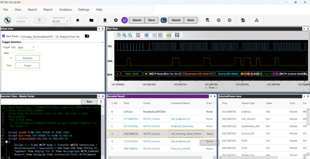
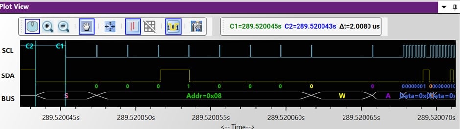
Figure 5: MCTP Primary to Secondary Transactions

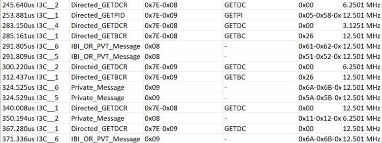
The decoded results are conveniently displayed in the Protocol listing and timing window of the accompanying software.

Case-2MCTP Packet Reading Based on Target IBI (Target to Controller)

The Transmission of MCTP packets from target to the Controller according to the IBI mode shall happen using the following general sequence as per the MCTP spec:

Target has an MCTP packet ready for transmission to the controller, it shall initiate an I3C IBI with MDB = 0xAE (as assigned in MIPI Mandatory Data Byte (MDB) Values Table registry) to inform the controller about the data ready. The controller shall read the MCTP packet (or multiple packets) from the Target using I3C Private Read transfer.

MCTP_over_I3C_packet_transfer_sequence_secondary_Primary_prodigy_technovations

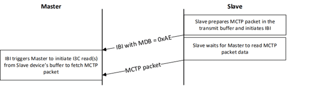
Figure 6:MCTP over I3C packet transfer sequence: secondary to Primary

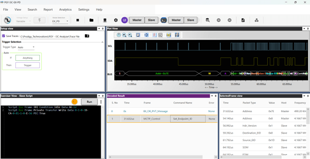
This scenario can be achieved by the PGY-I3C-EX-PD which enables users to configure both the controller and target devices. Upon receipt of the IBI from the target with the MDB 0xAE, the controller initiates reading of the target’s register (MCTP packet) using the Private Read command in response to the IBI signal as shown below.

In Analyzer Mode:

Testing interoperability across a diverse array of devices implementing MCTP over I3C is a crucial step in ensuring reliable communication and compatibility in multifaceted deployment scenarios. The PGY-I3C-EX-PD (Protocol Analyzer for I3C with MCTP Decode) plays a pivotal role in this rigorous testing process. By employing the PGY-I3C-EX-PD, testing engineers gain a powerful tool to systematically evaluate different MCTP implementations, identifying and resolving potential compatibility issues.

The user can monitor the MCTP packet by choosing the  ‘MCTP mode’ and the PGY analyzer gives the ability to analyze commands as per the MCTP specification thereby enabling designers to decode the issue effectively.

MCTP_mode_select_prodigy_technovations

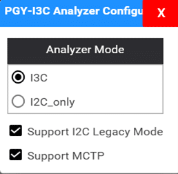
Figure 8: MCTP Mode Select

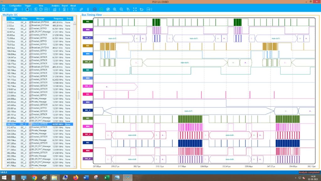
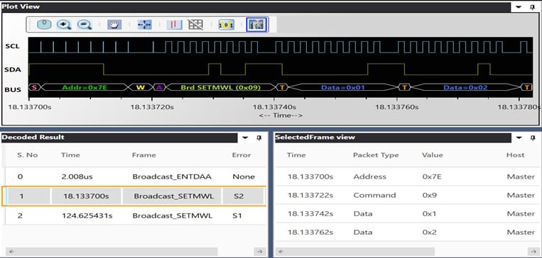
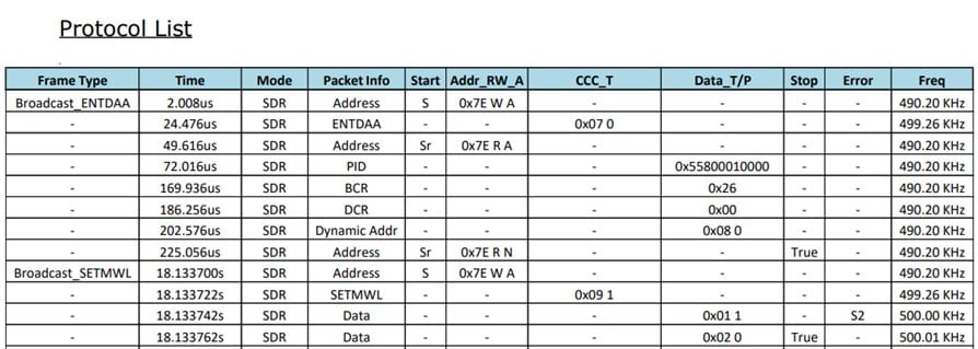
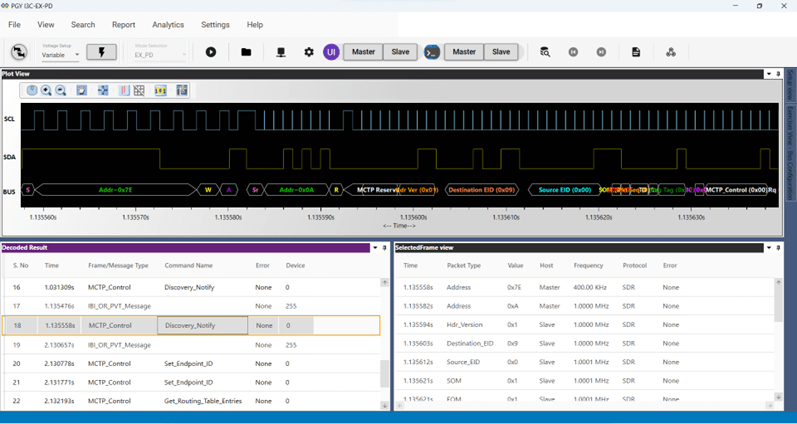
One of the key features of the PGY-I3C-EX-PD is its analyzer, which continuously sniffs the MCTP communication on the I3C bus. This thorough monitoring process captures the intricacies of the communication protocol, allowing the detection of any deviations from the standard along with the command names. The decoded results are then conveniently displayed in the Protocol listing and timing window of the accompanying software. This visual representation provides a comprehensive overview of the MCTP communication, helping engineers in understanding the data flow, analyzing protocol sequences, and pinpointing any deviation that may arise.

MCTP_analyzer_decode_prodigy_technovations

By leveraging the capabilities of the PGY-I3C-EX-PD in interoperability testing, developers and engineers can ensure that devices implementing MCTP over I3C can communicate seamlessly, thereby enhancing the reliability and performance of the overall system. The real-time monitoring and decoding capabilities of the PGY-I3C-EX-PD contribute to a streamlined testing process, allowing for efficient identification and resolution of any compatibility challenges that may arise during the integration of MCTP and I3C in diverse device ecosystems.

Serial Presence Detect (SPD) is a standardized method to automatically access the information about DDR3/4/5 memory modules. When a electronic system us powered on, it starts doing automatically configuring the system by identifying different hardware components. SPD is a feature in DDR3/4/5 enables the electronic system to know the DDR memory details and its timing information. DDR3/4 memory modules use SM Bus to provide this information. In case latest very high speed memory DDR5 uses low voltage signals (1V)  I3C interface to read the memory details and its timing information.

Multi I3C bus decoding for Serial Presence Detect (SPD) in DDR5

Fig 1. Typical I3C Bus architecture in DDR5 based system design


Typical I3C bus architecture is shown in Fig.1. When host controller is interfaced DDR5 modules using SPD5 hub. During the design and testing stage, it can be very challenging to monitor all the I3C bus in this architecture using off the shelf oscilloscopes.

Some of the key requirements to debug these designs as below

  1. Need logic analyser which can work with 1V signal amplitude.
  2. It should be possible to acquire different I3C logic activities at the same time.
  3. It should also possible decode all these I3C buses may be operating at different rate varying from 100KHz to 12.5MHz
  4. Monitor specific event in the I3C bus.


Prodigy Technovations has developed industry first multi-channel I3C decode solution on the existing logic analyser. It has following capabilities.

  1. Identifies logic levels at 1V signal amplitude.
  2. Decode eight I3C buses at the same time with time synchronization of all the I3C buses.
  3. Bus diagram for all the I3C buses
  4. Power full trigger capabilities
  5. Asynchronous sampling1GS/sec enables capturing varying clock rate I3C protocol events

PGY-LA-Multi-I3C is a 16 Channel logic analyser. Which has the following key capabilities

  • 1GS/Sec asynchronous sampling capabilities
  • Eight I3C Bus decoding capabilities
  • Trigger on I3C Protocol Packet content

Multichannel I3C Protocol decode analysis result view as shown in fig3.

Multi I3C bus decoding for Serial Presence Detect (SPD) in DDR5

Fig. 2. Listing of Multi I3C channel decode and digital timing diagram


Listing window list decodes the i3C packets from different I3C bus and displays it. Timestamp is used to list packet in the order so that user can the events happening with respect to the time.

Software also displays the timing waveform with bus diagram. Bus diagram will have each I3C packet information for easy debug purposes.

To capture the traffic at specific event, user can set the trigger condition based on I3C Protocol packet content.

Multi I3C bus decoding for Serial Presence Detect (SPD) in DDR5

Change Trigger condition for some other CCC or private

Fig. 3 I3C protocol Aware Trigger GUI


User can export this data to file in CSV format. This DATA can be viewed Excel software for further analysis

Multi I3C bus decoding for Serial Presence Detect (SPD) in DDR5

       Fig4. CSV export in Excel software


Exported data will time stamp, I3C bus name, protocol packet content and frequency of operation.

PGY-LA-Multi-I3C provides most comprehensive solution address the DDR5 system requirements for  serial peripheral detect bus. It can decode all eight channels with listing and timing diagram view.  Abilities to export this data makes it most convenient to use it.


Prodigy Technovations provides most comprehensive solution to develop I3C Technology. Following are our products.

PGY-I3C-EX-PD   I3C Protocol Exerciser and Analyzer with optional CTS: https://www.prodigytechno.com/device/i3c-protocol-analyzer/

PGY-I3C-EX-PD Lite I3C Protocol Exerciser and Analyzer with fixed voltage

PGY-I3C-USB-ADT I3C to USB adapter


Learn more about our comprehensive I3C solutions: https://www.prodigytechno.com/i3c-protocol-solutions/

I3C Solutions

Conquering the Timing Challenges in I3C communication with Prodigy’s Solutions!

One of the primary challenges in designing I3C Protocol communication is the occurrence of timing issues, which can cause communication errors. This will be challenging to debug for the engineers.  To address this, Prodigy Technovations Pvt. Ltd (Prodigy) provides an I3C Protocol Analyzer and Exerciser that provide precise timing analysis for reliable communication.

The timing and plot diagrams of the I3C Protocol Analyzer assist engineers in identifying the root cause of timing problems like inconsistent clock rates (or) timing mismatch. By analyzing the information, developers can fine-tune their designs to meet I3C timing specifications, ensuring accurate and error-free communication. Below is the snapshot of the timing measurement using the I3C Protocol Analyzer.

Figure 1: Accurate timing measurement of clock and data Signals of I3C Bus

During testing, most of the test cases will be related to data loss and protocol non-compliance in corner cases. These are intermittent problems difficult to acquire in test equipment.  Prodigy Technovations make I3C tester solutions that address these issues by continuously capturing and analyzing I3C protocol data and streaming it into the host computer storage system.

The PGY-I3C-EX-PD, Prodigy’s I3C Protocol Analyzer and Exerciser, supports continuous streaming of protocol activity to the host computer. It can generate and capture a vast amount of protocol traffic on the I3C bus using its substantial memory buffer. By analyzing the captured signals, Prodigy’s solution can detect timing violations, such as NACK responses from slave devices, and highlight the same in the report assisting engineers in real-time in solving the potential problems.

Below are the snapshots of Data representation with a waveform view of signals and report that shows errors.

Timing Challenges in I3C Protocol Communication

Figure 2: Plot view with Clock and Data representation along with the result windows

Timing Challenges in I3C Protocol Communication

Figure 3: Report generation sample with a data parity(S2) error

Interoperability issues due to timing mismatches can also hinder I3C testing. Prodigy’s solution plays a crucial role in resolving these issues efficiently. During the design cycle, interoperability testing is vital to ensure seamless functionality between devices from various vendors. Prodigy supports the defined MIPI standard Conformance Test, including the I3C Conformance Test Suite (CTS v1.1), enabling engineers to validate timing constraints and guarantee interoperability across devices.

The test engineers can perform regression testing using Prodigy’s API in Python / C++ for hours and analyze the captured I3C bus signals. This feature enables us to identify and address the issues that can occur randomly.

By combining these features, Prodigy offers a comprehensive solution to the timing challenges in I3C testing. It ensures precise timing analysis, optimizes clock rates, captures, and analyses signals to prevent data loss and protocol violations, validates timing constraints, and resolves interoperability issues efficiently.  Moreover, the feature of the solution is available in the same GUI software and the user can navigate between windows easily.

In conclusion, with the features and user-friendly software, the engineers can reduce their testing time (that might take days to weeks for complex issues) to meet their tight project schedule. It also ensures the quality of the product’s compliance with I3C bus standards that avoids post issues/failures in the field and leads to their end customer’s satisfaction.

Prodigy Technovations has been working on I3C technology since its inception. We have developed many technical contents to support our customers in developing and deploying I3C in many different applications.

Our I3C debugging solutions:

  1. I3C Protocol Analyzer and Exerciser
  2. I3C Electrical Validation Software
  3. I3C Protocol Decode Software
  4. Logic Analyzer for Embedded Interfaces

Introduction to I2C Protocol:

I2c protocol

I2C stands for Inter-Integrated circuit. It can also be referred to as IIC or I2C. I2C Protocol is a serial communication protocol, and it is widely used for short-distance communication. It provides simple and robust communication between the Peripheral device and the microcontroller.

I2C Protocol consists of two wires SDA and SCL which is bidirectional synchronous serial bus communication. Thus, I2C Protocol takes two wires for communication which also translates to low cost and this low cost has made I2C Protocol the most commonly used Serial Bus across most applications including IoT, consumer electronics, automotive, aerospace, and industrial equipment.

I2C Protocol is a synchronous protocol that allows a master to initiate communication with a slave device. I2C protocol is a master-slave communication where the master provides the clock which becomes the data transfer rate or clock frequency. It is a bi-directional bus meaning the master can write to the slave and read from the slave it is a serial bus which means data is a clock and it is shifted bit by bit and there are two bus lines serial clock (SCL) and serial data (SDA).

As u see in the diagram three slaves are connected to the same I2C Master and there is two pull-up resistor which is required for the I2C device to communicate properly this is because the I2C protocol works on the SCL and SDA bus lines which are an open drain or open collector the transmitting device just lets go of the I2C bus to create logic one and pulls or drives the line the ground to create logic 0.

In I2C Protocol there are 5-speed categories including standard mode, fast mode, fast plus mode, high-speed mode, and ultra speed mode these speed categories range from 100 kHz to 5MHz, where standard mode is 100KHz, Fast mode is 400KHz, Fast mode plus is 1MHz, High-Speed Mode is 3.4MHz and Ultra-fast mode is 5MHz. 100KHz up to 1MHz are very similar, while 3.4 MHz needs some special consideration, and 5MHz being unidirectional requires even more special attention. But the most common speed categories for I2C Protocol are Standard mode, Fast Mode, and Fast mode plus these modes are easy to implement.

I2C Protocol transactions are initiated with a start condition, the start condition is defined as the master driving SDA line low while SCL remains high, and note that it must be initiated with the I2C bus in an idle state means SDA and SCL lines are both high.

The slave address immediately follows the start condition, and it will be 7 bits or 10 bits long it should be noted that each device on the I2C bus needs a unique slave address. Next is the read-and-write bit, which immediately follows the slave’s address, this bit informs the slave if the master wants to read or write. 1 indicates the master wants to read from the slave and 0 indicates the master wants to write.

The next section is the Acknowledge bit and we can think of ack bits like a handshake between the master and slave and they occur on every 9th clock cycle, if ACK is 0 then data can be transmitted, and if ACK is 1 data cannot be sent. Next is the data byte which contains the information being transferred between the master and slave, It contains 8 bits of data.

The last section of the I2C protocol is the Stop condition all I2C transactions should be terminated with a stop condition, the stop condition is defined as the master releasing the line while the SCL signal level is high after a stop condition the I2C bus will remain in idle state and won’t be free for the next I2C transaction.

There are two important concepts of I2C Protocol: I2C Arbitration and I2C Clock Stretching

I2C Arbitration: I2C Protocol is a multi-master bus it can be possible that multiple masters are driving the bus simultaneously, If one of them detects SDA is low when it should be high, it assumes that another master is active and immediately stop its transfer.


I2C Clock Stretching: The master wants to send the data where the slave is not ready to receive data so the  I2c slave pulls the SCL line low.

Advantages:

  • I2C Protocol supports multi-master, multi-slave communication
  • It uses only two wires
  • In I2C Protocol ACK/NACK functions can be proved useful for error handling
  • Adaptable as it can adapt to the needs of various slave device
  • In I2C Protocol the addressing is very simple and does not need any CS lines to add extra devices like SPI Protocol
  • It uses flow control

Disadvantages:

  • I2C Protocol is a half-duplex mode of communication
  • The hardware complexity increases when the number of master/slave devices is more in the circuit
  • Many devices have multiple addresses stored which can cause conflicts

Applications of I2C Protocol:

  • Accessing DACs and ADCs
  • Reading certain memory ICs
  • Reading hardware sensors
  • Communicating with multiple micro-controller
  • Transmitting and controlling user-directed actions

Debug I2C Protocol:

Prodigy also offers an I2C Protocol analyzer to capture and decode the I2C packets. The I2C protocol analyzer has the advanced capability not only to trigger but long allow very long captures which is very useful for the embedded design engineer during the debugging.

I2C Protocol Analyzer

Prodigy I2C Protocol Analyzer

About the Author

Royal Samson D Souza is an Application Engineer at Prodigy Technovations. He graduated from NMAM Institute of Technology in 2022 with a bachelor’s degree in Electronics & Communication Engineering. His area of interest includes Embedded systems, Digital System Design, and Automotive Electronics.

Sensor Challenges in Next Generation Consumer Devices, IOT, and Automotive Design.

Over the last decade, we have seen an explosion of mobile phone devices along with sensors on the devices. Right from accelerometers, gyroscopes, ambient light, proximity, infrared, humidity, and temperature. These sensors are great for the consumer experience from the system integration poses a challenge. Consumers are demanding every device to be as smart as a smartphone. Hence the demand for sensor integration into consumer devices has grown exponentially. Each of these sensors requires an interrupt and hence dedicated GPIO pins are taken away from the system designer.

In case the system or 15 Sensors, 15 pins of the chip need to be dedicated to the sensors interface only. Adding to the challenge is the kind of functionality sensors manufacturers are adding to the sensors. Modern-day sensors require higher bandwidth for data transfers.

To the rescue comes I3C Protocol Analyzer. I3C Protocol Analyzer is a MIPI standard supporting inband interrupts. Its backward compatibility with I2C, SPI, and inband interrupt saves the dedicated GPIO pin for the system designer. However, as the number of sensors added to consumer device increases. The Debug of the sensor is a new challenge during the board bring-up or Firmware Debug. There is a need to not only understand which sensor interface is misbehaving it’s also required to know the sequence of the transaction.I3C also supports dynamic addressing with devices needing to enumerate and assign addresses. This increases the need for advanced debugging and analysis of the protocol. The engineers need to be equipped to handle the new complexity added new I3C MIPI standard.

If you need help with I3C Debug and I3C Protocol Analysis, Prodigy is here to help. Prodigy offers I3C Protocol Analyzer and Exerciser. Prodigy is a very active contributor to the MIPI Alliance and the MIPI Sensor Workgroup, making contributions to the specifications such as I3C, MIPI PHYs, CSI, DSI, UniPro, and more.

What is MIPI I3C?

The MIPI I3C Bus interface is an evolutionary specification that builds upon the legacy I2C standard. The aim is to reduce the number of physical pins used in sensor system integration and supports low-power, high-speed digital communication typically associated with UART and SPI interfaces so that I3C becomes a single interface combining all the capabilities of the legacy interfaces.

Advantage of I3C

I3C Protocol has a multi-drop bus which, at 12.5 MHz, is over 12 times faster than what I2C supports while using significantly less power.

I3C Protocol’s main features include:

  • Backward compatibility with legacy I2C
  • Multi-Master and Multi-drop capabilities
  • Dynamic Addressing
  • In-Band Interrupts
  • Hot-Join support

The I3C Protocol interface is expected to play a fundamental role in streamlining sensor integration in smartphones, Internet-of-Things (IoT) devices, and wearables. I3C can also be used to manage complex systems as and when designers migrate to a common management transport which drastically reduces cost and latency in such complex systems while also enabling new capabilities.

MIPI I3C Theory of Operations: I3C Protocol

All I3C Protocol communications occur within a frame. The frame begins with a START, followed by one or more transfers, and a STOP.
The I3C interface supports Single Data Rate (SDR) messages which are similar to I2C Messages. The maximum clock speed is 12.5MHz. It also supports high data rate (HDR) messages. In HDR, data transfer is equivalent to clock cycles. There are two types of messages Broadcast and Direct common command code (CCC) messages which allows the master to communicate with all or specific slave on the bus.
I3C protocol is based on the frame encapsulation approach. The I3C frame always includes START, the Header, the data, and the STOP. The I3C bus is always initialized in SDR mode and never in HDR mode.
Common Command Code (CCC) commands protocol is formatted using only SDR. CCC is transmitted to specific to slaves or all slaves in the I3C bus. CCC General format is shown in this figure.

For the HDR modes:

  • First the dedicated Broadcast I3C address(7’h7E) is issued to all slaves on the I3C bus.
  • Then one of the Enter HDR CCCs is issued, indicating that the Master is entering the HDR mode. Each HDR mode has its own Enter HDR CCC.
  • This is followed by one or more HDR transfers.
  • HDR mode is ended by using the HDR exit pattern protocol.

For more details on I3C protocols, please refer to MIPI® I3C specifications.
I3C devices have Bus and Device characteristic registers which will hold information about the capabilities of I3C devices.
I3C bus can be configured with multiple devices. These devices are I3C Main Master, I3C Secondary Master, I3C Slave, and I2C Slave.

I3C devices may have many features appropriate for their function in the I3C bus. Depending on the I3C Bus system’s need, it may not be necessary that all features are enabled for any particular bus instantiation. Enabled features of every I3C device shall be described in the characteristic register of the device. Master obtains the characteristic register info during the power-up state of the I3C bus.

At the start-up stage from power-down, the main master shall assign a unique dynamic address to every device on the bus including itself. Dynamic address creates a priority ranking of device interrupts. If any secondary master present in the I3C bus shall be made aware of dynamic address and characteristic registers.

I3C-based electronic hardware design involves the design of I3C Master, I3C Slave, and I3C system designs. These designs offer different challenges at different stages of the design cycle. Design engineers need a tool to debug the I3C device for reliable operations. Some of the important requirements are

  • Designers who are developing master or slave, need a fully working Master or Slave device which designers can configure and test their designs.
  • Make sure I2C devices can co-exist with I3C bus
  • They need a tool that will capture the communication between Master and slave and analyze the protocol traffic for protocol errors
  • Need a tool to capture protocol traffic at a specific event. These events could be anticipated error conditions or protocol activity
  • Emulate the I3C bus using the designed Master or Slave device in the I3C network

Where is I3C Protocol being used?

I3C protocol is used as a de-facto standard for integrating sensors in the System. Temperature sensors, gyroscopes, etc. There are new interesting applications for I3C interfaces in data centers as management buses.

Debugging I3C Tools :

When working with I3C, it is important to have the right set of tools to ensure the I3C design is implemented properly. Having a logic analyzer and oscilloscope is always helpful to debug complex hardware timing issues. There are cheaper tools available in the market to test I3C, however, limited in capability.

A logic analyzer is an excellent tool to debug when implementing and designing the I3C Bus. This can help you understand the protocol packet-level issues.

An oscilloscope is helpful in case you want to measure the timing parameters of the I3C Device.

I3C protocol analyzer can be very helpful to do I3C packet sniffing. Prodigy Technovations also offers an I3C Electrical Validation, and I3C Protocol Decode Software to debug your I3C packets using a Tektronix oscilloscope.

How does Prodigy Technovations Interfaces with I3C?

Prodigy Technovations has several different tools that interface with the I3C protocol. All the I3C tools fall into two different areas. The protocol analyzer monitors the traffic that is happening on the bus. The exerciser allows users to interface directly with I3C System and drive I3C Data.

Benefits of Prodigy’s I3C Protocol Exerciser and Analyzer:

  • Ability to configure it as Master or Slave
  • Ability to configure PID, BCR, and DCR registers
  • Supports legacy I2C slaves and Master
  • Generate different I3C and I2C SDR and HDR Packets
  • Flexibility to upgrade the unit TSP and TSL encoding (When it is available)
  • Error Injection such as CRC errors, parity errors, and ACK/NACK errors
  • Variable I3C data speeds
  • Simultaneously generate I3C traffic and Protocol decode of the Bus
  • Timing diagram of Protocol decoded bus
  • Listing view of Protocol activity
  • Error Analysis in Protocol Decode
  • State Machine view of the I3C packets
  • Ability to write exerciser script to combine multiple data frame generation at different data speeds
  • USB2/3 host computer interface
  • Flexibility to upgrade to the unit for evolving I3C Specification


I3C Test Setup

I3C Test Setup

Embedded System Testing :

Embedded Systems have multiple devices and each of the devices uses the bus to communicate with the main chip or processor and other devices in the system. The Embedded system generally has SPI or I2C device to communicate with the EEPROM device and I3C to communicate with the sensor interface. The protocol analyzer can be very useful to debug and validate the embedded system and figure out failures of any of the devices in the embedded system.

Post-silicon validation:

During the chip development process, Once the Chips is back from the foundry all the interface of the Chip or SoC needs to be tested. Most of the SoC or chips have I2C, SPI, and I3C or eMMC based on the application of the chip. The Protocol analyzer is a very handy tool for the hardware validation engineer to debug the bus interfaces.

Pre-Silicon validation:

In chip or SoC development, before the chip is taped out its engineering manager needs to get the confidence development of the chip, Emulation platforms like Zebu or Palladium are commonly used to do the hardware validation. The protocol analyzer can be a very useful assist tool for the emulation engineer to check for the sanity of the communication interface like I2C and SPI along with the emulation Platform.

What are the various types of Protocol analyzers used in SoC or embedded System Development?

I2C Protocol Analyzer:

I2C or IIC (Inter-Integrated Circuit) is the most commonly used communication interface between two devices. This is the simple two-wire protocol used to communicate between the Integrated Circuits in the embedded system. An I2C Protocol analyzer plays very important in the debugging of the I2C Bus interface.

SPI Protocol Analyzer:

SPI Serial Peripheral Interface is the most commonly used communication interface between two devices, similar to I2C but for higher speeds of transfer. An SPI Protocol analyzer plays very important in the debugging of the SPI Bus interface.

SPMI Protocol Analyzer:

SPMI (System Power Management Interface) is standard with a 2-wire synchronous serial, bidirectional interface that connects the integrated Power Controller(PC) of a System on- Chip (SoC) processor system with one or more Power Management Integrated Circuits (PMIC) voltage regulation systems. An SPMI Protocol analyzer plays very important in the debugging of the SPMI Bus interface.

I3C Protocol Analyzer:

I3C serial bus interface is emerging as a chosen interface for all future sensor connectivity in the mobile phone and automotive Industry. An I3C Protocol analyzer plays very important in the debugging of the I3C Bus interface.

RFFE Protocol Analyzer:

The RF Front-end control interface (RFFE) serial bus interface is used for controlling RF frond-end devices. There is a variety of front-end devices such as Power Amplifiers (PA), Low-Nose Amplifiers (LNA), filters, switches, power management modules, and antenna tuners. It is widely used in mobile devices. An RFFE Protocol analyzer plays very important in the debugging of the RFFE Bus interface and mobile subsystems.

eMMC Protocol Analyzer:

emmC Protocol Analyzer enables design and verification engineers to test and debug SD, SDIO, and eMMC by triggering command, response, data, or CRC errors. An eMMC Protocol analyzer plays very important in the debugging of the eMMC Bus interface and mobile subsystems.

UFS 4.0 Protocol Analyzer:

UFS 4.0 Protocol Analyzer offers capture and debugging of data across MPHY, UniPro, and UFS 4.0 protocol layers. A UFS 4.0 Protocol analyzer plays very important in the debugging of the UFS Bus interface and mobile subsystems.

Automotive Ethernet Protocol Analyzer:

Automotive Ethernet interface is used in-vehicle bus communication and also to support feature-rich ADAS in smart and connected vehicles. An Automotive Ethernet Protocol analyzer plays very important in the debugging of the Ethernet Bus interface in a connected Vehicle.

What are the various Features of the Protocol analyzer?

The protocol analyzer comes with the following features :

  • Triggering: Each of the protocol analyzers and equipped with various kinds of triggers, multi-level triggers, multiple consecutive event triggers, etc.
  • Protocol Layer support: The protocol analyzer tool has complete support for protocol analysis. All the layers of the protocol are analyzed.
  • Traffic Generator: The protocol analyzer generates protocol-specific data and timing and gives the validation engineer complete control of data and timing. The traffic generator also can generate back-to-back traffic on the communication bus.
  • Error Injection: The protocol analyzer is also equipped with error injection capability. Bit error test patterns can be generated and sent over the communication channel.

How to Integrate Protocol Analyzer in the Development Environment?

The protocol analyzer provides access to API libraries. These APIs can be integrated into the development environment and an advanced level of validation and testing can be achieved. The API can be used to generate traffic on the communication bus as well as capture the traffic on the communication Channel.

What is Prodigy doing to advance in the Protocol analyzer market?

Prodigy Technovations regularly looks at the new trends in the market and comes up with a new set of products for the Protocol analyzer market. Prodigy Technovations has an expert team working on the latest cutting-edge technologies and Prodigy Technovations is going to lead the market in the coming years.

<PRODIGY’S PROTOCOL ANALYZERS

If you are in the market for buying or choosing a Protocol Analyzer, how do you know which one is the right one for you? There are many options to choose from and looking at the various technical specifications can be a daunting task. This article gives you some factors to consider when considering your purchase.

  • Protocol Specification support: There are various protocols like I2C, SPI, and I3C. First is to know the kind of protocol to be analyzed and debugged in your design. Make sure the latest protocol specification is supported and the protocol analyzer is backward compatible.
  • Protocol Analysis: The protocol analyzer needs to have the ability to do lower-layer and upper-layer protocol analysis and decode the captured packet. The software of the protocol analyzer needs to give a good view of the underlying packet and captured protocol sequence.
  • Trigger Capability: A good protocol analyzer can set complex and nested triggers. Understanding the trigger level and capability will help you select the right protocol analyzer for you.
  • Protocol Search: The protocol analyzer needs to have the ability to search some sequence of the protocol sequence.
  • Capture duration: During complex engineering debugging a very long capture sequence is required to do the analysis. Hence having a very large capture can be an added advantage.
  • Host Interface: USB 2.0 is the most commonly used interface for the protocol analyzer some of them also have interfaces to the network using gigabit Ethernet.
  • Error Injection: The protocol analyzer needs to have the ability to introduce various kinds of protocol errors to test the communication interface or bus.
  • Traffic Generation: Generating various kinds of traffic is very important for the protocol analyzer, back-to-back traffic data on the bus can help decode corner cases design issues in the system.

Other Features to Consider

  • Support: Once you have the protocol analyzer in your hand and run into issues during debugging you will need a good team to support the debug issues in hand. Every company offers various levels of support.
  • Shipping Lead Time: Once the protocol analyzer is ordered the product needs to be shipped to the development location. Please check the lead times well in advance before ordering.
  • Year of development: It’s always good to pick up a product that is stable in the market and used by many customers already.
  • Ease of Use: Most of the protocol analyzers are used to debug hard engineering problems and ease of use and integration into the development environment are very important features for the product.

Conclusion:

Choosing a Protocol Analyzer can be a daunting task, and this guide will help you easily navigate the process of selecting the protocol analyzer. As the complexity of the protocol increases so does the cost of the product.

Prodigy offers an I3C protocol analyzer, a UFS 4.0 protocol analyzer, an I2C/SPI protocol analyzer, and many more products that support advanced features like API integration to provide long capture for debugging and the ability to reflash and keep the specification features up to date. Do Visit our Product Page Below for the Newest Product Updates.

<Protocol Analyzer

5 Questions You Should Ask When Choosing a Protocol Analyzer:

When choosing a Protocol Analyzer most engineers or managers ask for basic questions like protocol specification support and the kind of trigger required on the bus. However, these are five very important questions that are asked only by experienced validation engineers. The five important questions are as follows:

Question 1: Does the Protocol Analyzer support Simultaneous debugging?

Most of the time during the design validation process, the bus protocol packet not only needs to be captured but also needs to be analyzed at the same time. Very few protocol analyzers support this feature. Having simultaneous analysis and decoding can speed up your debugging significantly.

Question 2: Does the Protocol Analyzer Firmware (FW) upgrade as the specification evolves?

The latest protocol specifications are always evolving and a few fixes and supports are regularly added to the specification. The protocol analyzer needs to not only support the current version of the specification but also support the future upgrades that happen in the protocol specification.

Question 3: How does one view the protocol analysis packet?

State machine view is the best view one can get for the protocol analysis. Engineers are used to looking at state machine views to decode and understand protocol analysis. Some of the complex protocols having a clean state machine view will help you quickly decode the packet or protocol issues.

Question 4: Does the Protocol Analyzer support API Integration?

The engineering development environment is very complex. Integration of the new protocol analyzer tool into the environment is key to running long regressions and decoding the hard problems. API support by the protocol analyzer plays a key role in the integration into the development environment.

Question 5: What is the form factor?

Some of the protocol analyzers need to have a small form factor so that they can be easily deployed on the field. Having a small form factor also helps the engineer have more space in the workbench area so that space can be deployed for further complex testing by adding additional equipment.

Conclusion:

Choosing the right Protocol Analyzer is a daunting task and a protocol analyzer is an expensive set of capital equipment added to your organization. It’s always recommended to ask for a demo of the unit and work with the application engineer before finalizing the protocol analyzer

Prodigy offers an I3C protocol analyzer, I2C/SPI protocol analyzer, UFS4.0 protocol analyzer, and many more protocol analyzers that support advanced features like API integration to provide long capture for debugging and the ability to reflash and keep the specification features up to date. Check out our Product Page with the latest products.

<PROTOCOL ANALYZERS

Request For Quote

Share your requirement and our team will provide a tailored quote based on your validation needs.

"*" indicates required fields

This field is for validation purposes and should be left unchanged.
Address*

Request For Demo

Tell us your use case and our team will schedule a product demo aligned to your validation workflow.

"*" indicates required fields

This field is for validation purposes and should be left unchanged.
Address*

Request A Demo

Tell us your use case and our team will schedule a product demo aligned to your validation workflow.

"*" indicates required fields

This field is for validation purposes and should be left unchanged.
This field is hidden when viewing the form
Address*

Request Quote

Share your requirement and our team will provide a tailored quote based on your validation needs.

"*" indicates required fields

This field is for validation purposes and should be left unchanged.
Address*